Accumulator

Inactive Publication Date: 2009-03-12
BORGWARNER TORQ TRANSFER SYSTEMS AB
View PDF18 Cites 8 Cited by
  • Summary
  • Abstract
  • Description
  • Claims
  • Application Information

AI Technical Summary

Benefits of technology

[0004]It is an object of the present invention to mitigate, alleviate or eliminate one or more of the above-identified deficiencies and disadvantages singly or in any combination. This is in one aspect achieved by an accumulator for a hydraulic system, wherein the accumulator comprises a liner, a piston and a housing, defining a pressure chamber, for receiving hydraulic fluid at high pressure, wherein the piston is biased towards an end position of the pressure chamber for interacting with the hydraulic fluid in the pressure chamber, and the piston is movable in a predetermined range for accumulating hydraulic fluid. The accumulator furthermore has at least one outlet port in a sidewall of the liner which outlet port is covered by the piston in said predetermined range and is uncovered when the piston has moved a predetermined distance from the end position. In one embodiment, the liner around the pressure chamber may be made of a polymeric material, such as poly phenylene sulfide

Problems solved by technology

This may result in an unnecessarily high load being imposed on the pu

Method used


Image

  • Accumulator
  • Accumulator
  • Accumulator

Examples


Embodiment Construction

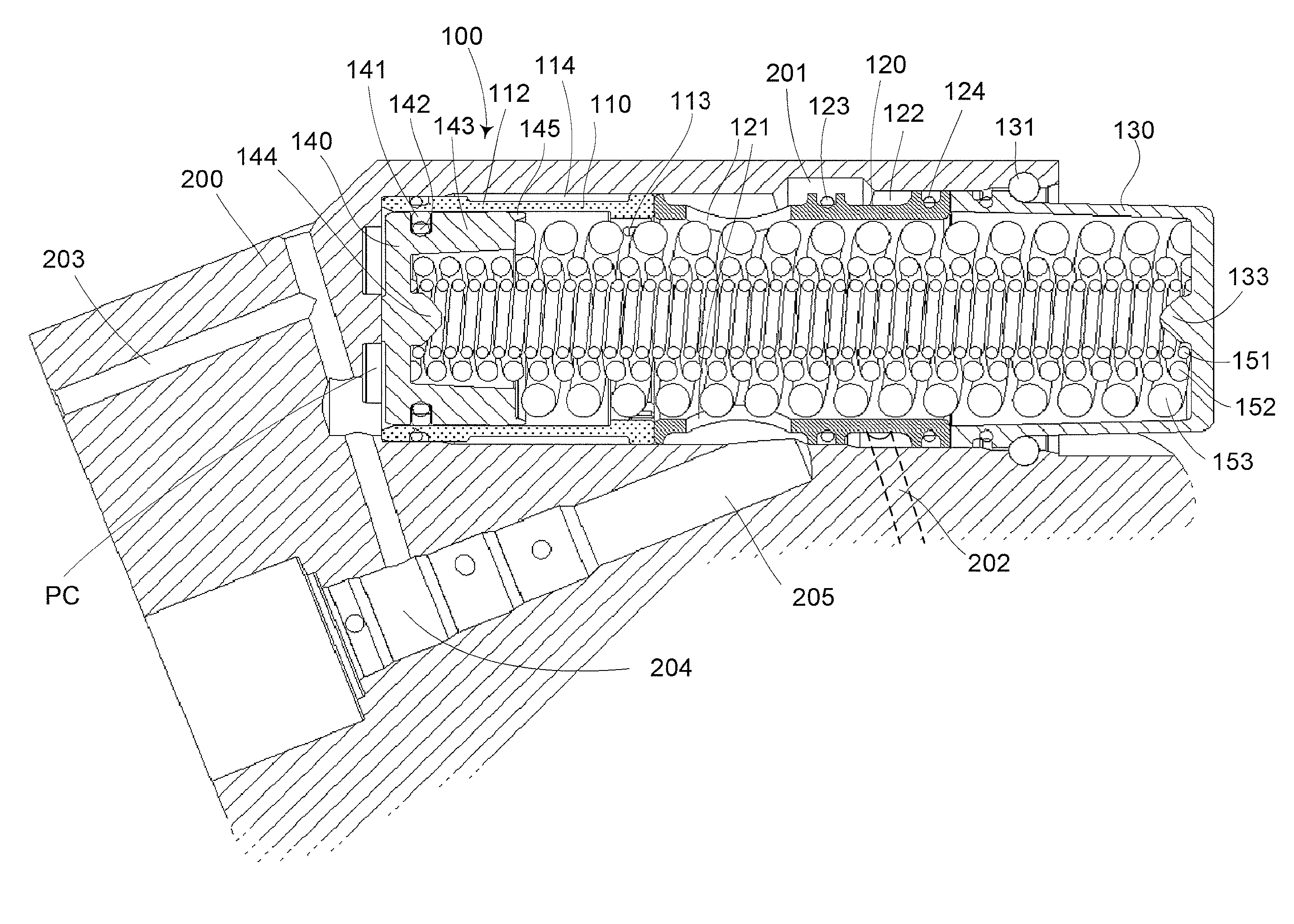
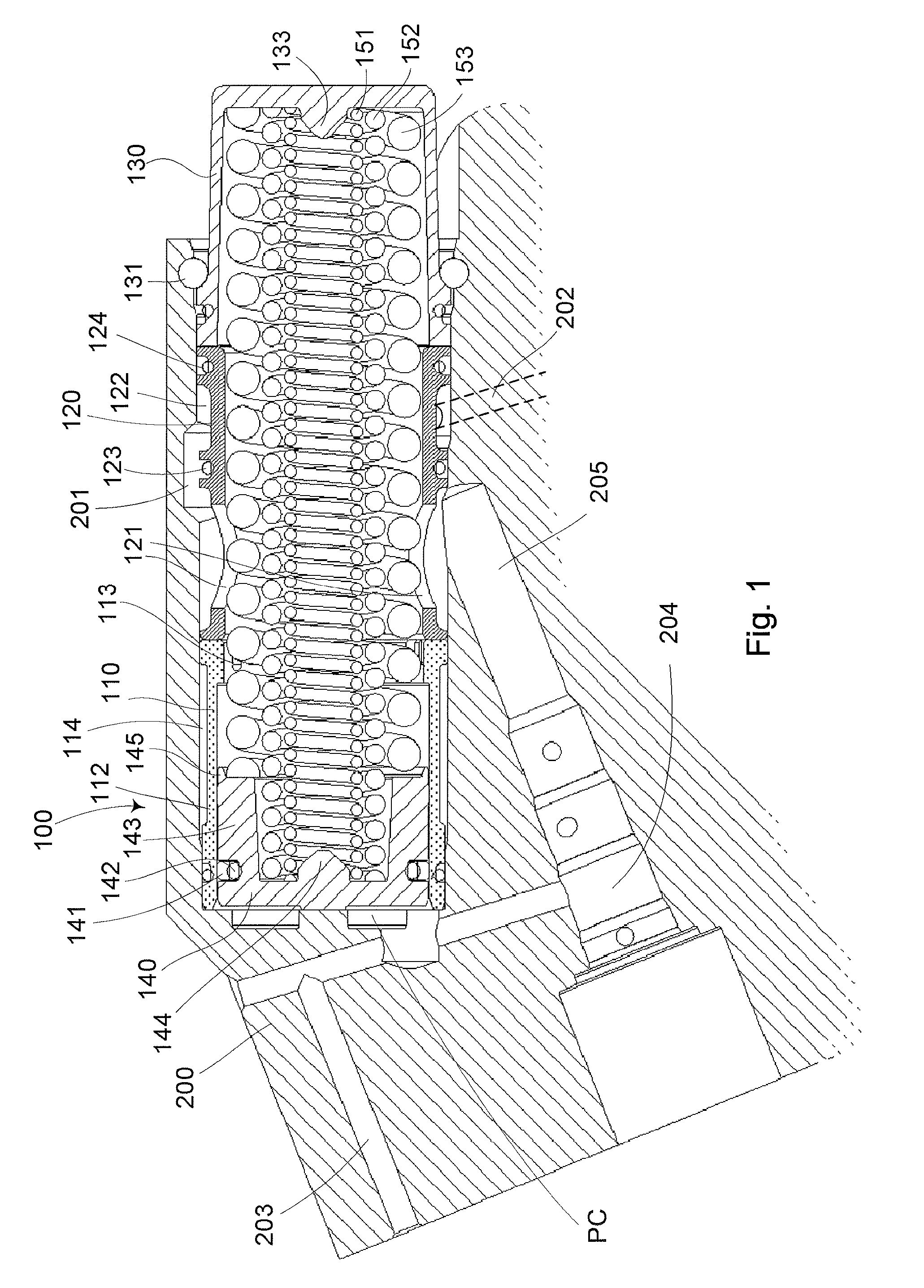
[0012]Below, several embodiments of the invention will be described with references to the drawings. These embodiments are described for illustrative purposes only, in order to enable a skilled person to carry out the invention and to disclose the best mode. However, such embodiments do not limit the invention. Moreover, other combinations of the different features are possible within the scope of the invention.

[0013]An accumulator 100 according to an embodiment of the present invention is shown in a sectional view in FIG. 1, mounted in a housing 200. The accumulator 100 includes, in the shown embodiment, a body comprising three parts, namely a liner 110, a spacer 120 and a lid 130, all being substantially cylindrical having a substantially circular cross-section. The liner 110 cooperates with a piston 140, which is adapted for reciprocating movement within the liner 110.

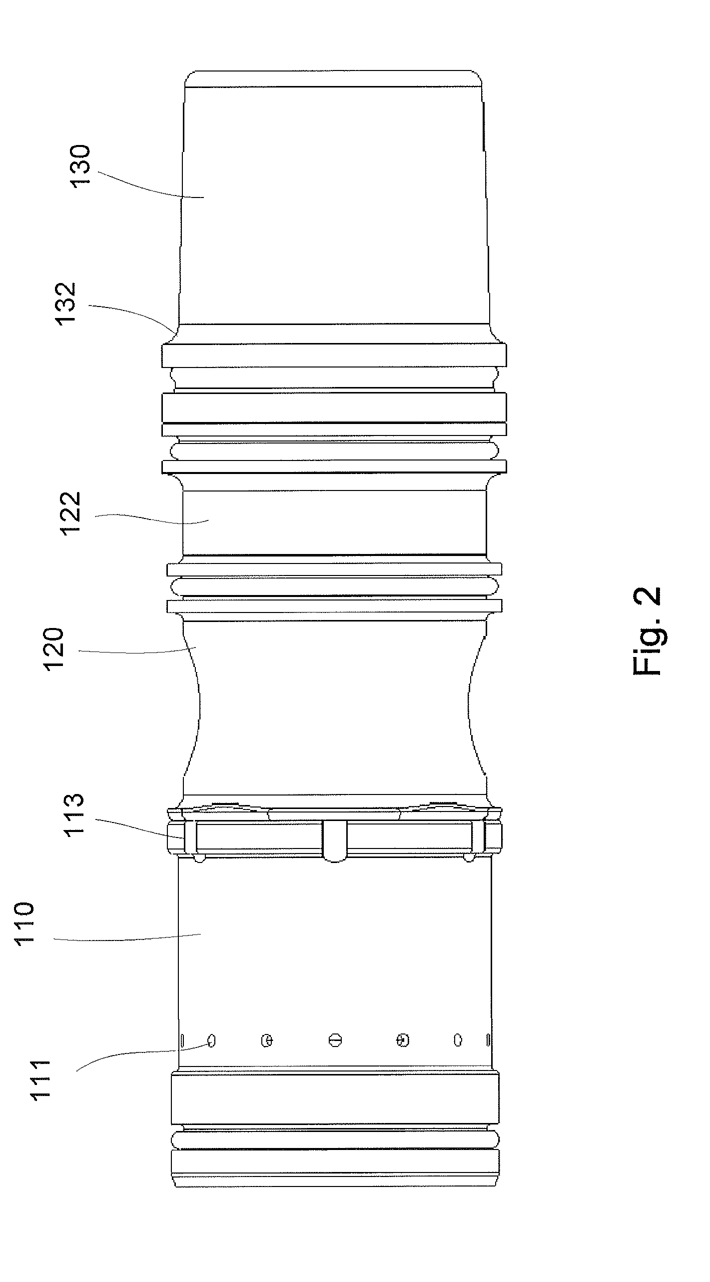
[0014]The liner 110 is formed with one or several outlet ports 111, see FIG. 2, which are located in a sidewall 1...


PUM


Abstract

An accumulator for a hydraulic system, wherein the accumulator comprises a liner, a piston and a housing, that defines a pressure chamber, for receiving hydraulic fluid at high pressure, wherein the piston is biased towards an end position of the pressure chamber for interacting with the hydraulic fluid in the pressure chamber, and the piston is movable in a predetermined range for accumulating hydraulic fluid. The accumulator has at least one outlet port in a sidewall of the liner, which outlet port is covered by the piston in the predetermined range and is uncovered when the piston has moved a predetermined distance from the end position. A hydraulic system is also provided that comprises the above accumulator and an all-wheel drive system comprising the above hydraulic system. A method for de-airing an accumulator according to above is also provided.

Description

CROSS-REFERENCE TO RELATED APPLICATIONS[0001]The present application is a continuation of pending International patent application PCT / EP2007 / 050565 filed on Jan. 19, 2007 which designates the United States and claims priority from Swedish patent application 0600524-3 filed on Mar. 10, 2006, the content of which is incorporated herein by reference.FIELD OF THE INVENTION[0002]The present invention relates to an accumulator for a hydraulic system and a method of de-airing a hydraulic system comprising such an accumulator. It furthermore relates to a hydraulic system and an all-wheel drive system incorporating said hydraulic system.BACKGROUND OF THE INVENTION[0003]Hydraulic systems are normally equipped with a pump that provides high-pressure oil to actuators and control valves. An accumulator can be connected to the high-pressure side where it inter alia can serve to remove pressure fluctuations in the hydraulic system. The pressure at the high-pressure side should be limited, though,...

Claims


Application Information

Patent Timeline
IPC IPC(8): F16L55/04F16D31/02
CPCF15B1/021F15B1/04F15B21/044F15B2201/413F15B2201/31F15B2201/4053F15B2201/411F15B2201/21F15B1/24B60K17/34
Inventor DAVIDSSON, PER-OLOF
Owner BORGWARNER TORQ TRANSFER SYSTEMS AB
Why Eureka
Try Eureka