Gravity Gradiometer System

a gravity gradiometer and system technology, applied in the field of gravity gradiometers, can solve the problems of additively corrupting tensor measurements, unable to enable the measurement of additional gradients, and completely eliminating such rotations

Inactive Publication Date: 2009-03-12
LOCKHEED MARTIN CORP
View PDF28 Cites 34 Cited by
  • Summary
  • Abstract
  • Description
  • Claims
  • Application Information

AI Technical Summary

Benefits of technology

[0047]The present invention provides improved gravity gradiometers that are immune to one or more

Problems solved by technology

But they do not enable the measurement of additional gradients.)
It is impossible, however, to completely eliminate such rotations, and tensor measurements will be additively corrupted by the presence of gradient signals due to these rotations.
Yet, it is subject to a variety of error mechanisms that can adversely affect its performance.
The net misalignment, in the axial and radial directions, of the accelerometers on a disc can severely impact system performance.
Although mechanical alignment of the accelerometer sensitive axes is carefully adjusted prior to commissioning the gradiometer, misalignments routinely remain.
But tangential realignment is not possible.
Unfortunately, axial and tangential alignments are not independently adjustable.
The instrument errors, though no longer having power spectral density peaks coinciding with the modulated gravity gradient signals, still corrupt measurements at harmonics of the rotation rate and nearby frequencies.
The strength of the instrument errors near harmonics of the rotation rate and near DC reduced the accuracy of the measurements at corresponding frequencies.
By way of example, DC errors in the instrument frame cause the measurements of gradients near twice the rotation rate to be unusable.
Part of the difficulty in manufacturing gravity gradiometers comes from the need to balance, to a high degree, signal components of the various accelerometers composing the gradiometer measurement.
This is

Method used


Image

  • Gravity Gradiometer System
  • Gravity Gradiometer System
  • Gravity Gradiometer System

Examples


Embodiment Construction

[0070]Accelerometer Misalignment

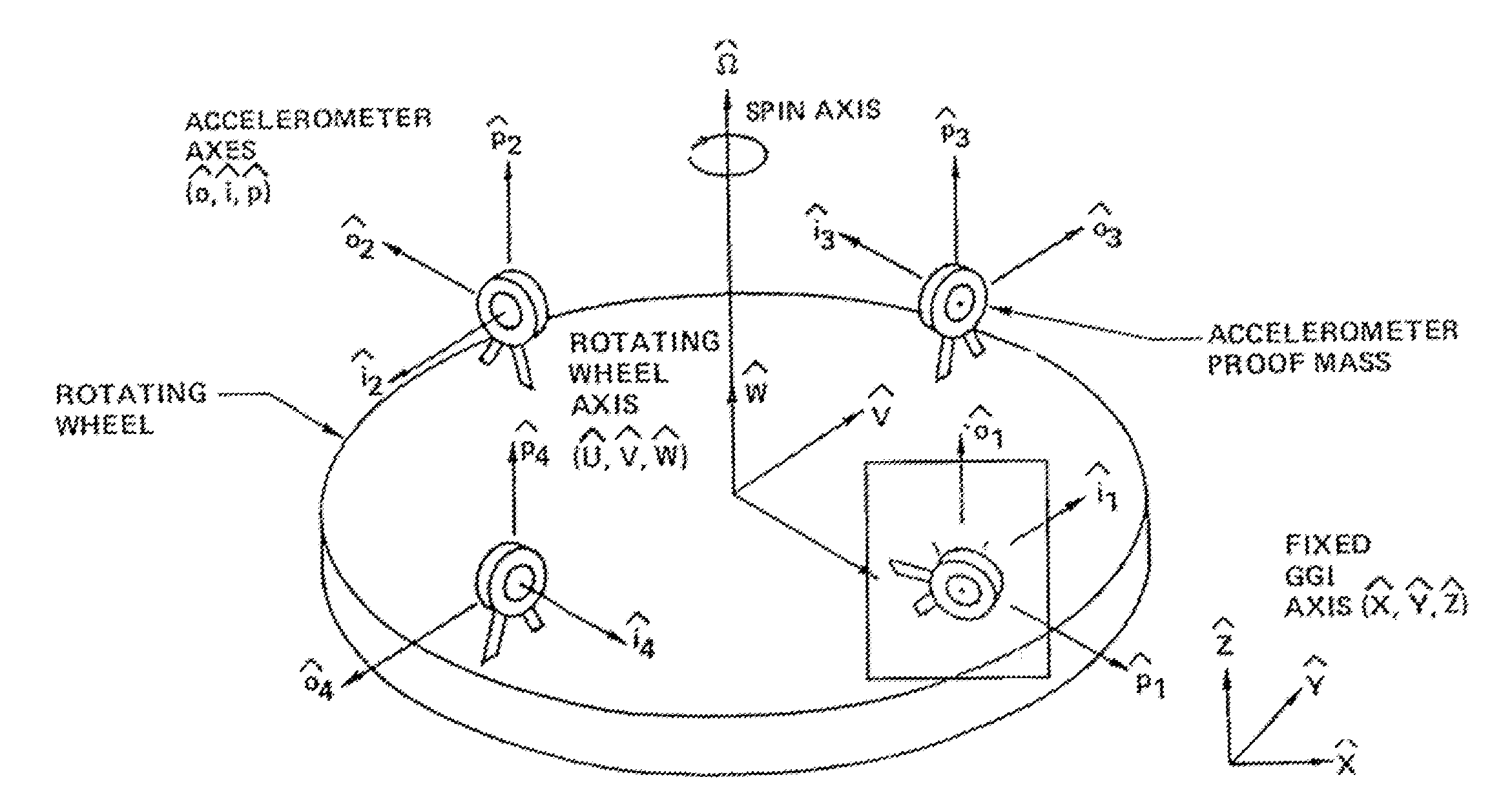
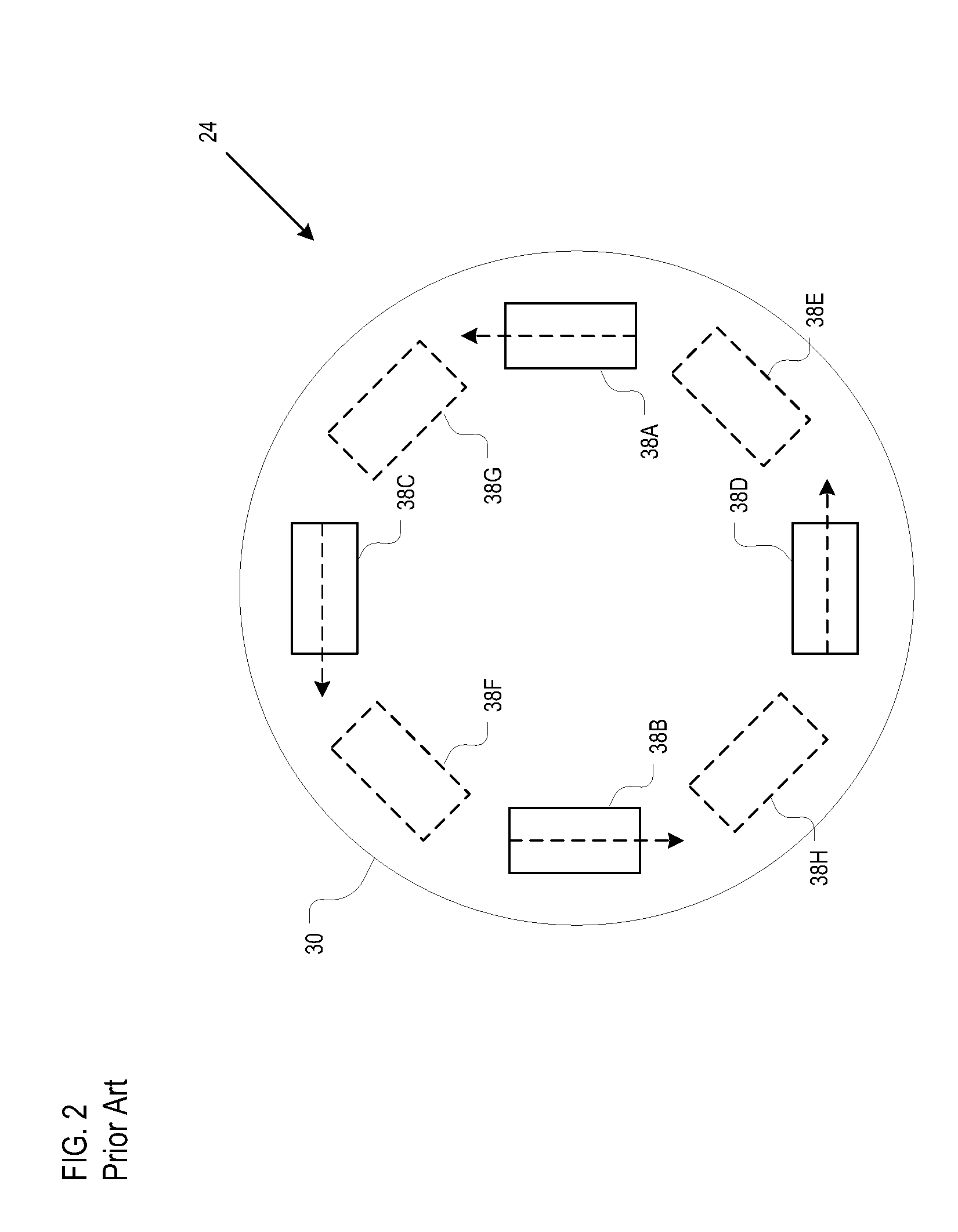
[0071]FIG. 4 depicts the proof mass support arrangement in the prior art wherein the pendulous axes (Pi) aligns with the spin axis W. As previously disclosed, the net misalignment, in the axial and radial directions, of the accelerometers on a disc can severely impact system performance. In prior-art mounting arrangements, axial and tangential alignments are not independently adjustable.

[0072]Misalignments of individual accelerometers are of far less concern than the net misalignments of the four accelerometers in a gradiometer complement. As a consequence, if the accelerometers are mounted on the disc such that their pendulous axes have differing components in the axial and tangential directions, it is possible to electronically adjust the null positions of the individual accelerometers to enable independent net realignment in both directions (i.e., axial and tangential).

[0073]FIG. 5 depicts a proof mass support arrangement in accordance with the ill...


PUM


Abstract

A methods and apparatus for an improved gravity gradiometer are disclosed.

Description

STATEMENT OF RELATED CASES[0001]This case claims priority of U.S. Pat. Application Ser. No. 60 / 970,505 filed Sep. 6, 2007, which is incorporated by reference herein.FIELD OF THE INVENTION[0002]The present invention relates to gravity gradiometers.BACKGROUND OF THE INVENTION[0003]Gravitational potential is a scalar quantity that represents the energy associated with a unit mass in a gravitational field. The gravitational field is a vector field that describes the spatial variations in potential. In the context of the Earth, local variations in the gravity field are caused, for example, by deviations in the surface of the Earth from a geometric sphere, surface and subsurface geology, water tides, atmospheric tides, and the change in the relative position of the earth, moon, and the sun.[0004]A gravitational field can be decomposed into three mutually-orthogonal components Γx, Γy, Γz shown in FIG. 1. For reference, a coordinate system is used in which the X-axis corresponds to the nort...

Claims


Application Information

Patent Timeline
IPC IPC(8): G01V7/00
CPCG01V7/00
Inventor METZGER, THOMASSIERACKI, DAVID L.DOSCH, DANIEL E.
Owner LOCKHEED MARTIN CORP
Why Eureka
Try Eureka