
Sail wing with high span efficiency and controlled pitching moment

a technology of wing span efficiency and control moment, which is applied in the direction of hang glider aircraft, wing shape, transportation and packaging, etc., can solve the problems of large spar mass, large nose down pitching moment, and significant tension on the flexible membrane of the sail to control the shap

Active Publication Date: 2009-03-12
AURORA FLIGHT SCI CORP
View PDF17 Cites 3 Cited by
  • Summary
  • Abstract
  • Description
  • Claims
  • Application Information

AI Technical Summary

Benefits of technology

[0010]It is therefore a general aspect of the invention to provide a wing structure that will obviate or minimize problems of the type previously described.

Problems solved by technology

However, the flexible membrane of the sail requires significant tension to control its shape, both in camber and twist.
To reduce twist and / or camber, more tension is needed, which means more compression and bending in the spar, which increases the spar mass.
While this is good for production of lift, it also gives a large nose down pitching moment.
The spanwise curve results in significant twist in the wing, which results in outer half of the wing being very poor at producing lift.
Further still, the non-uniform distribution of lift means that the wing has a lift distribution that produces greater drag due to lift.
More wing area means more weight, which can result in less usable load.
Thus, while sail wings are conceptually simple, they tend to have poor performance.

Method used


Image

  • Sail wing with high span efficiency and controlled pitching moment
  • Sail wing with high span efficiency and controlled pitching moment
  • Sail wing with high span efficiency and controlled pitching moment

Examples


Embodiment Construction

[0027]The various features of the preferred embodiments will now be described with reference to the drawing figures, in which like parts are identified with the same reference characters. The following description of the presently contemplated best mode of practicing the invention is not to be taken in a limiting sense, but is provided merely for the purpose of describing the general principles of the invention.

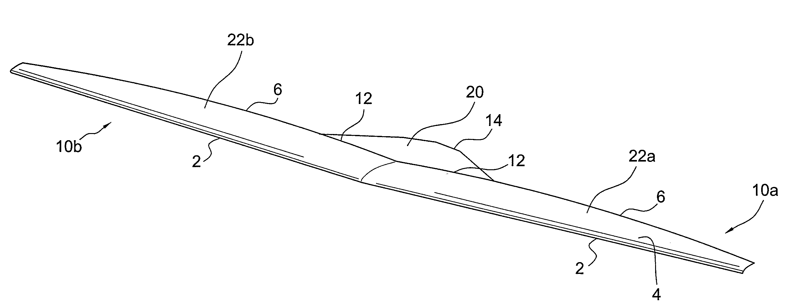
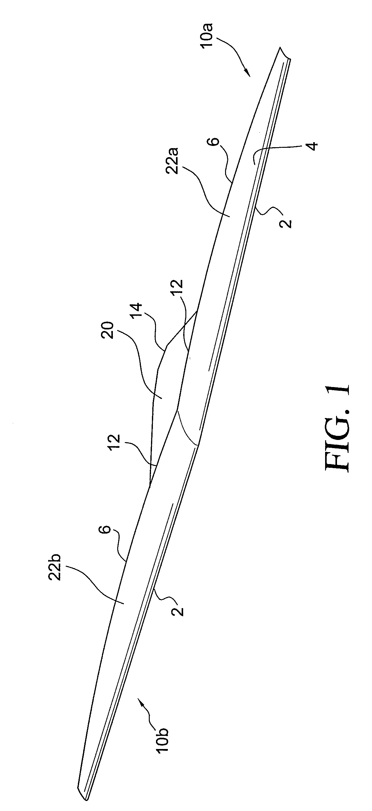
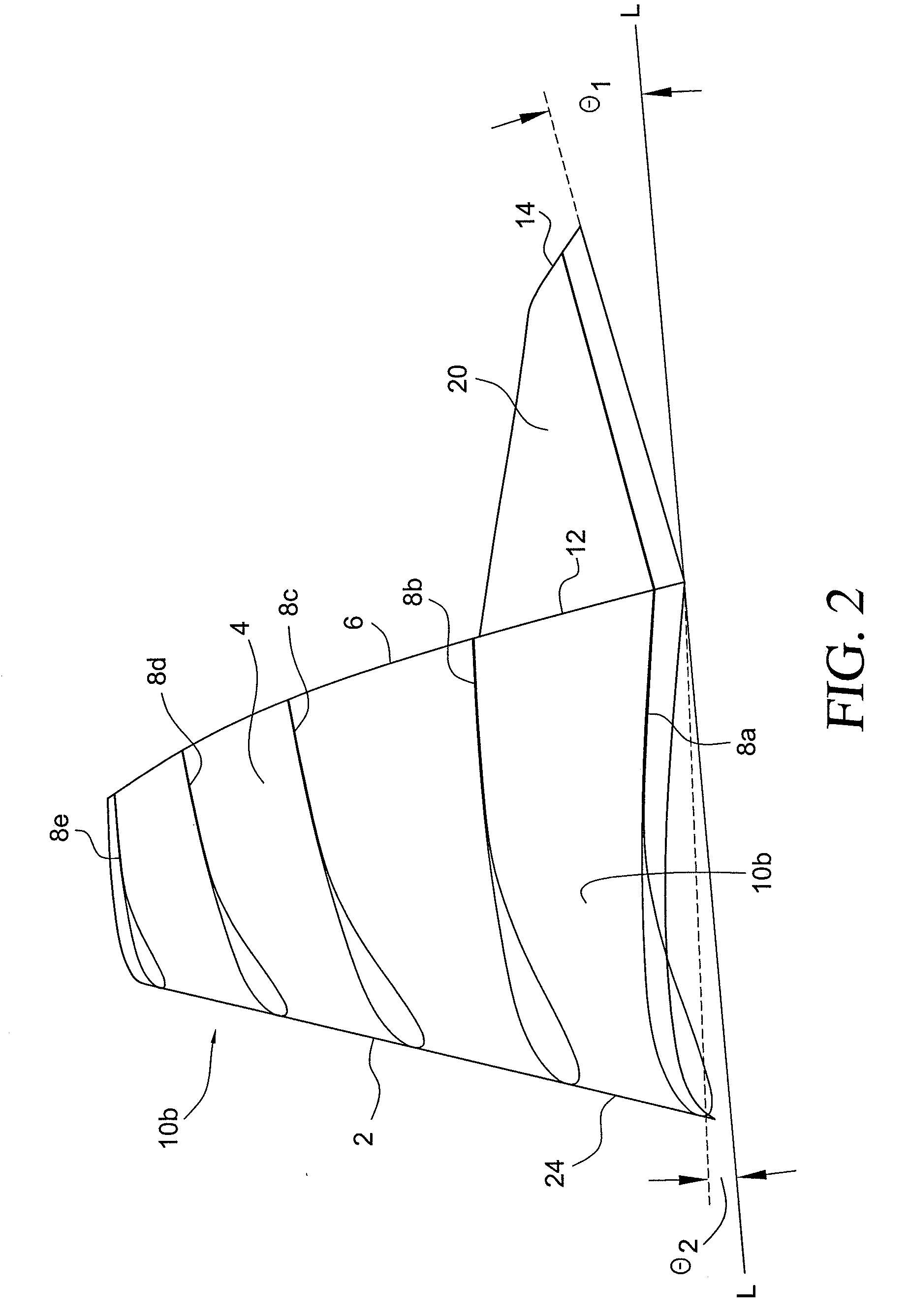
[0028]Wing surface extension 20, as shown and described in the accompanying figures, combined with main sail wing 10, provides light weight aircraft 50 (light weight aircraft is defined to be less than about 5,000 lbs.) with a high efficiency lifting surface (i.e., high coefficient of lift) and low net pitching moment with only a slight increase in complexity.

[0029]Most sail wings have very high taper (small tip chord relative to the root chord). A high degree of taper plus the spanwise twist results in very high lift at the root and very low outboard lift. This is one of the...


PUM


Abstract

An aircraft comprising a fuselage, a sail wing appended to the fuselage, the sail wing having a sail wing root chord length, and wherein the sail wing includes a sail wing leading edge spar, a sail wing membrane attached to the sail wing leading edge spar, and a sail wing trailing edge wire located at a trailing edge of the sail wing membrane, the aircraft further comprising a wing surface extension, located aft and at an inboard area of the sail wing trailing edge wire, the wing surface extension having a wing surface extension root chord length, and wherein the wing surface extension includes a wing surface extension membrane attached to the sail wing trailing edge wire, and a wing surface extension trailing edge, and wherein the wing surface extension trailing edge is reflexed such that the wing surface extension trailing edge is positioned upwards at a first angle with respect to a plane formed along a centerline of the aircraft and along the lower surfaces of the sail wing. The wing surface extension is further configured to affect a reduced nose-up pitching moment, and to produce a more even coefficient of lift along the wing of the aircraft.

Description

PRIORITY[0001]The present application claims priority under 35 U.S.C. § 119(e) to U.S. Provisional Patent Application Ser. No. 60 / 943,832 filed Jun. 13, 2007, the entire contents of which are herein expressly incorporated by reference.BACKGROUND OF THE INVENTION[0002]1. Field of the Invention[0003]The invention is related to light weight aircraft. More particularly, the invention is related to a system and method for improving wing span efficiency and pitching control moments on lightweight aircraft.[0004]2. Background Art[0005]Sail wings have been proposed for light weight aircraft in the past, and are commonly used on hang gliders. One advantage of sail wings is that they allow a large amount of wing area to be folded up and stowed in a small volume.[0006]However, the flexible membrane of the sail requires significant tension to control its shape, both in camber and twist. Even then, large twist angles can occur along the span, as the sail forms catenary type curves to convert its...

Claims


Application Information

Patent Timeline
Patent Type & Authority Applications(United States)
IPC IPC(8): B64C3/14
CPCB64C3/10Y02T50/12B64C31/028Y02T50/10
Inventor PARKS, ROBERT
Owner AURORA FLIGHT SCI CORP
Learn More