Check patentability & draft patents in minutes with Patsnap Eureka AI!

Trace evidence detection using multiple laser light sources

Inactive Publication Date: 2009-03-12
COHERENT INC
View PDF11 Cites 18 Cited by
  • Summary
  • Abstract
  • Description
  • Claims
  • Application Information

AI Technical Summary

Benefits of technology

[0006]The present invention is directed to a method of detecting trace evidence materials on a surface. In one aspect the inventive method comprises irradiating the surface with radiation from at least first and second lasers. The first and second lasers emit radiation at respec

Problems solved by technology

One disadvantage of this is that not all materials in the range may be equally detectable.
Another disadvantage is that, fingerprint detection aside, it may not be clear what trace materials are being detected.

Method used


Image

  • Trace evidence detection using multiple laser light sources
  • Trace evidence detection using multiple laser light sources
  • Trace evidence detection using multiple laser light sources

Examples


Embodiment Construction

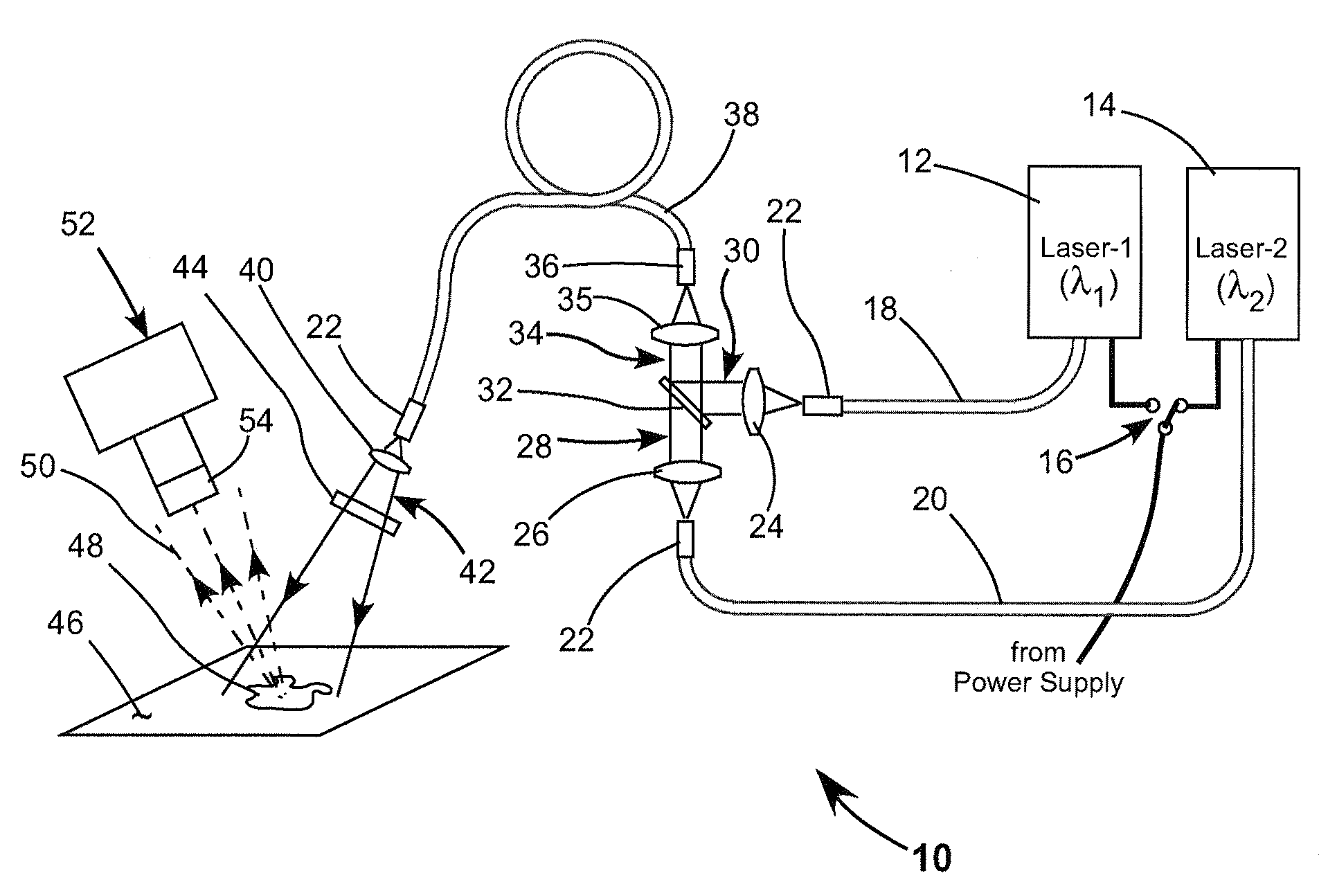
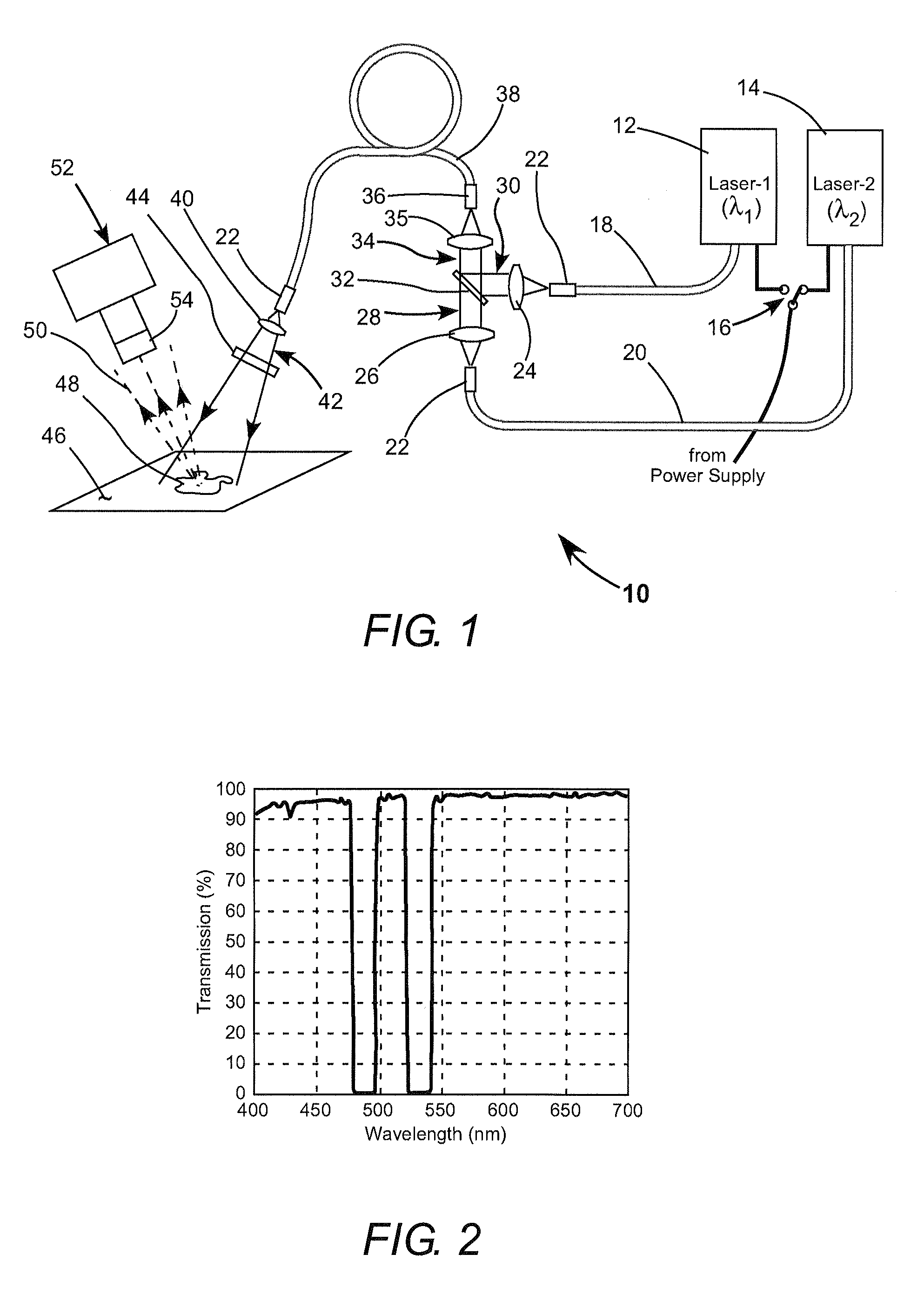
[0013]Referring now to the drawings, wherein like features are designated by like reference numerals, FIG. 1 schematically illustrates a preferred embodiment 10 of trace evidence detection apparatus in accordance with the present invention. Apparatus 10 includes first and second lasers 12 and 14, respectively. Lasers 12 and 14 emit laser radiation at wavelengths λ1 and λ2, respectively. The output power of the lasers is selectively variable. Lasers 12 and 14 are powered by current from a power supply not shown. Power is directed alternatively to one or the other laser by a switch 16.

[0014]Radiation from lasers 12 and 14 is delivered via optical fibers (or optical fiber bundles) 18 and 20, respectively. Each fiber (bundle) is terminated by a ferrule 22 from which the radiation is delivered from the fiber. A positive lens 24 collimates radiation from fiber 18 into a collimated beam 30. A positive lens 26 collimates radiation from fiber 20 into a collimated beam 28. Beams 28 and 30 are...


PUM


Abstract

A method for detecting trace evidence materials on a surface comprises irradiating the surface with radiation from two or more lasers emitting radiation at different wavelengths selected to stimulate luminescence in the trace materials. The evidence is detected by observing the surface through an optical filter arranged to transmit the luminescence, while blocking transmission of the laser radiation wavelengths reflected or scattered from the surface.

Description

PRIORITY CLAIM[0001]This application claims priority of U.S. Provisional Application No. 60 / 993,185, filed Sep. 10, 2007, the complete disclosure of which is hereby incorporated by reference.TECHNICAL FIELD OF THE INVENTION[0002]The present invention relates in general to trace evidence detection using optical radiation stimulated luminescence. The invention relates in particular to stimulating the luminescence using radiation at a plurality of different wavelengths.DISCUSSION OF BACKGROUND ART[0003]Laser radiation is increasingly being used in crime scene investigation for detecting trace evidence such as fingerprints or bodily fluid residue. Generally a surface being investigated for such trace evidence is irradiated by laser radiation having a wavelength that is absorbed by trace material being sought and will stimulate fluorescence or luminescence characteristic of the material. The laser-radiation-irradiated surface is observed, usually in a darkened environment, through an opt...

Claims


Application Information

Patent Timeline
IPC IPC(8): G01N21/64
CPCG01J3/02G01J3/0218G01J3/0227G01J3/427G01J3/4406G01N21/645G01N2201/0634G01N2021/6419G01N2021/6421G01N2021/646G01N2021/6471G01N2021/6484G01N21/6486
Inventor HUNZIKER, LUKASHERINK, GEORGLEPERT, ARNAUD
Owner COHERENT INC
Features
  • R&D
  • Intellectual Property
  • Life Sciences
  • Materials
  • Tech Scout
  • Unparalleled Data Quality
  • Higher Quality Content
  • 60% Fewer Hallucinations
Learn More