Transformer Structure

a transformer and structure technology, applied in the direction of transformer/inductance details, inductances, electrical devices, etc., can solve the problem of high leakage inductance, and achieve the effect of increasing the leakage inductance overall

Inactive Publication Date: 2009-03-12
DELTA ELECTRONICS INC
View PDF2 Cites 7 Cited by
  • Summary
  • Abstract
  • Description
  • Claims
  • Application Information

AI Technical Summary

Benefits of technology

[0009]The primary objective of this invention is to provide a transformer structure, which comprises multiple magnetic circuits, so that the the overall leakage inductance is increased. In addition, independent magnetic circuits for the primary coils and the secondary coils can also be provided.

Problems solved by technology

However, for high-voltage transformers, a high leakage inductance is typically needed to meet the resonance frequency requirements.

Method used


Image

  • Transformer Structure
  • Transformer Structure
  • Transformer Structure

Examples


Embodiment Construction

[0016]A detailed description of a transformer structure of this invention will be made hereinafter with reference to the attached drawings and specific embodiments thereof.

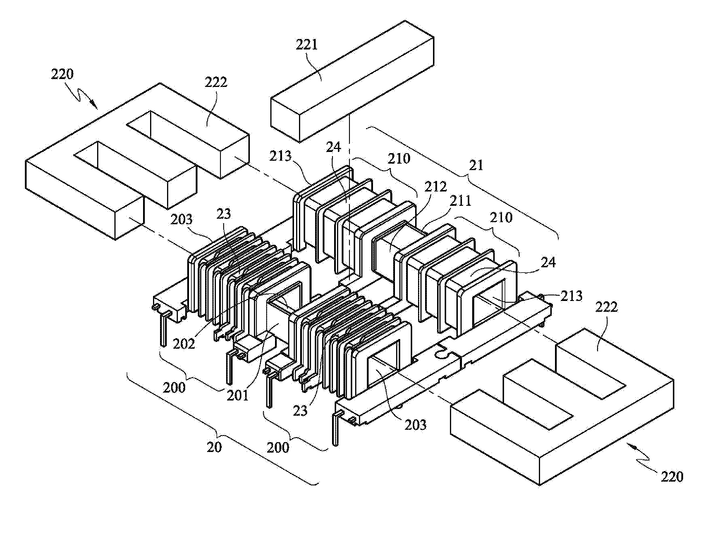
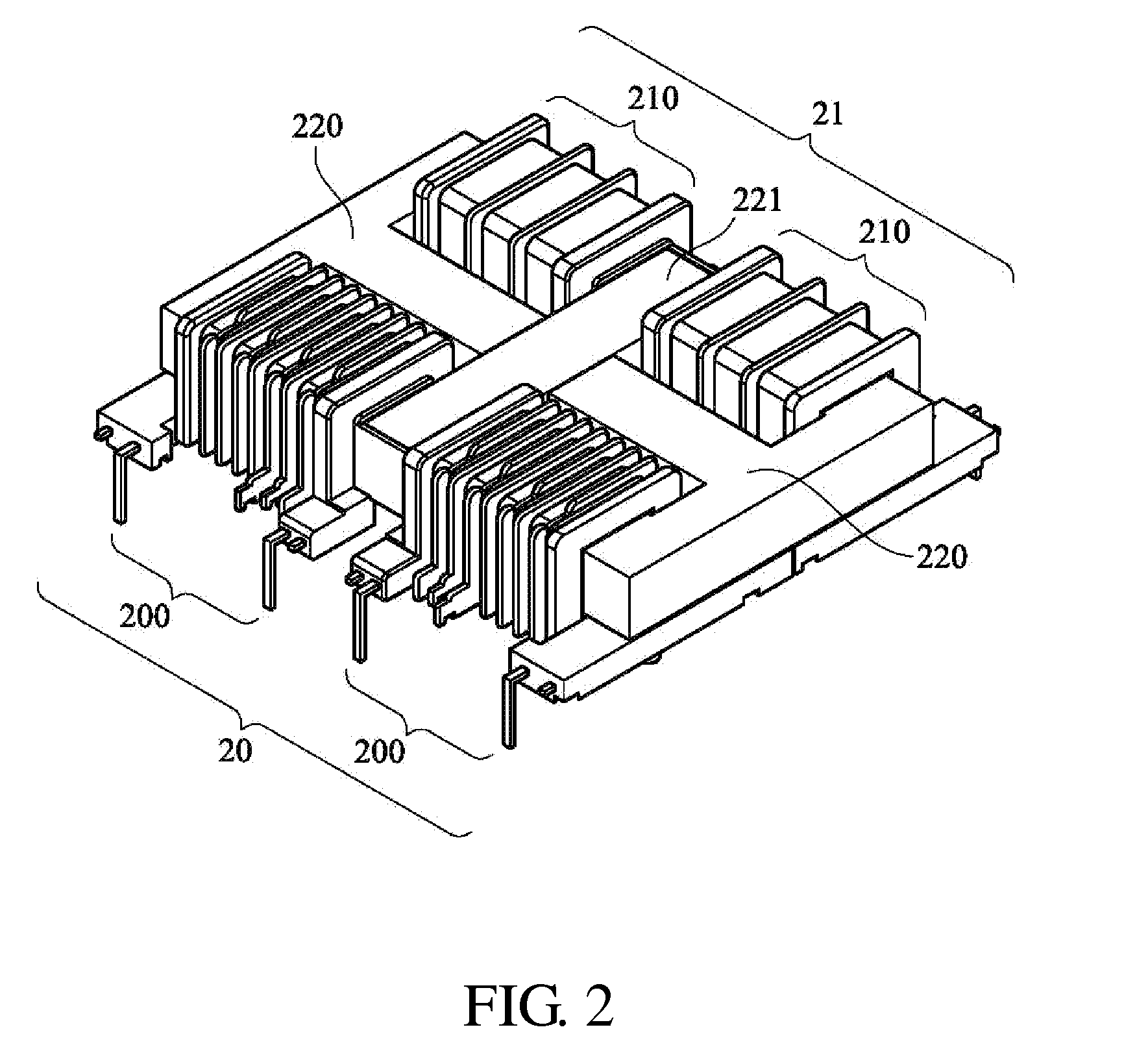
[0017]As shown in FIGS. 2 and 3, a preferred embodiment of this invention is a transformer structure, which comprises a first winding frame 20 and a second winding frame 21. The first winding frame 20 and the second winding frame 21 are coupled to each other via a binding site to form a transformer base. The first winding frame 20 has a jack 203, and the second winding frame 21 has a jack 213. Two primary coil assemblies 23 are wound around the first winding frame 20, and two secondary coil assemblies 24 are wound around the second winding frame 21. The iron core assembly comprises two first iron cores 220 and a second iron core 221. The first iron cores 220 are inserted into the jack 203 of the first winding frame 20 and the jack 213 of the second winding frame 21. The first winding frame 20 has two more primary ...


PUM

PropertyMeasurementUnit
leakage inductanceaaaaaaaaaa
voltageaaaaaaaaaa
resonanceaaaaaaaaaa

Abstract

A transformer structure is provided. The transformer structure comprises at least one first winding frame, at least one second winding frame, a plurality of primary coil assemblies which are wound around the at least one first winding frame, a plurality of secondary coil assemblies which are wound around the at least one secondary winding frame, and an iron core assembly which is placed in the jacks of the at least one first winding frame and the at least one second winding frame. The at least one first winding frame has a plurality of primary coil areas, around which the primary coil assemblies are wound. The at least one second winding frame has a plurality of secondary coil areas, around which the secondary coil assemblies are wound.

Description

[0001]This application claims the benefit of priority based on China Patent Application No. 200720177106.4, filed on Sep. 8, 2007, the contents of which are incorporated herein by reference in their entirety.CROSS-REFERENCES TO RELATED APPLICATIONS[0002]Not applicable.BACKGROUND OF THE INVENTION[0003]1. Field of the Invention[0004]The present invention relates to a transformer structure, more particularly, relates to a transformer structure that can increase the leakage inductance of a transformer.[0005]2. Descriptions of the Related Art[0006]As shown in FIG. 1, a conventional transformer comprises a first winding frame 10, a second winding frame 11, and an iron core 12. The first winding frame 10 has a first primary coil portion 100 and at least two first secondary coil portions 101. The second winding frame 11 is assembled with the first winding frame 10, and has a second primary coil portion 110 and at least two second secondary winding portions 111. The two primary coils are wou...

Claims


Application Information

Patent Timeline
Patent Type & Authority Applications(United States)
IPC IPC(8): H01F27/30
CPCH01F27/306H01F38/08H01F27/325
Inventor CHIH, LEE HUANG
Owner DELTA ELECTRONICS INC
Why Eureka
Try Eureka