
Display apparatus and driving method thereof

a technology of display apparatus and driving method, which is applied in the direction of static indicating device, electroluminescent light source, instruments, etc., can solve the problems of deteriorating display image quality and convergence of turn-on current of driving transistor, and achieve the effect of preventing aberration of white balan

Inactive Publication Date: 2009-03-12
CANON KK
View PDF17 Cites 31 Cited by
  • Summary
  • Abstract
  • Description
  • Claims
  • Application Information

AI Technical Summary

Benefits of technology

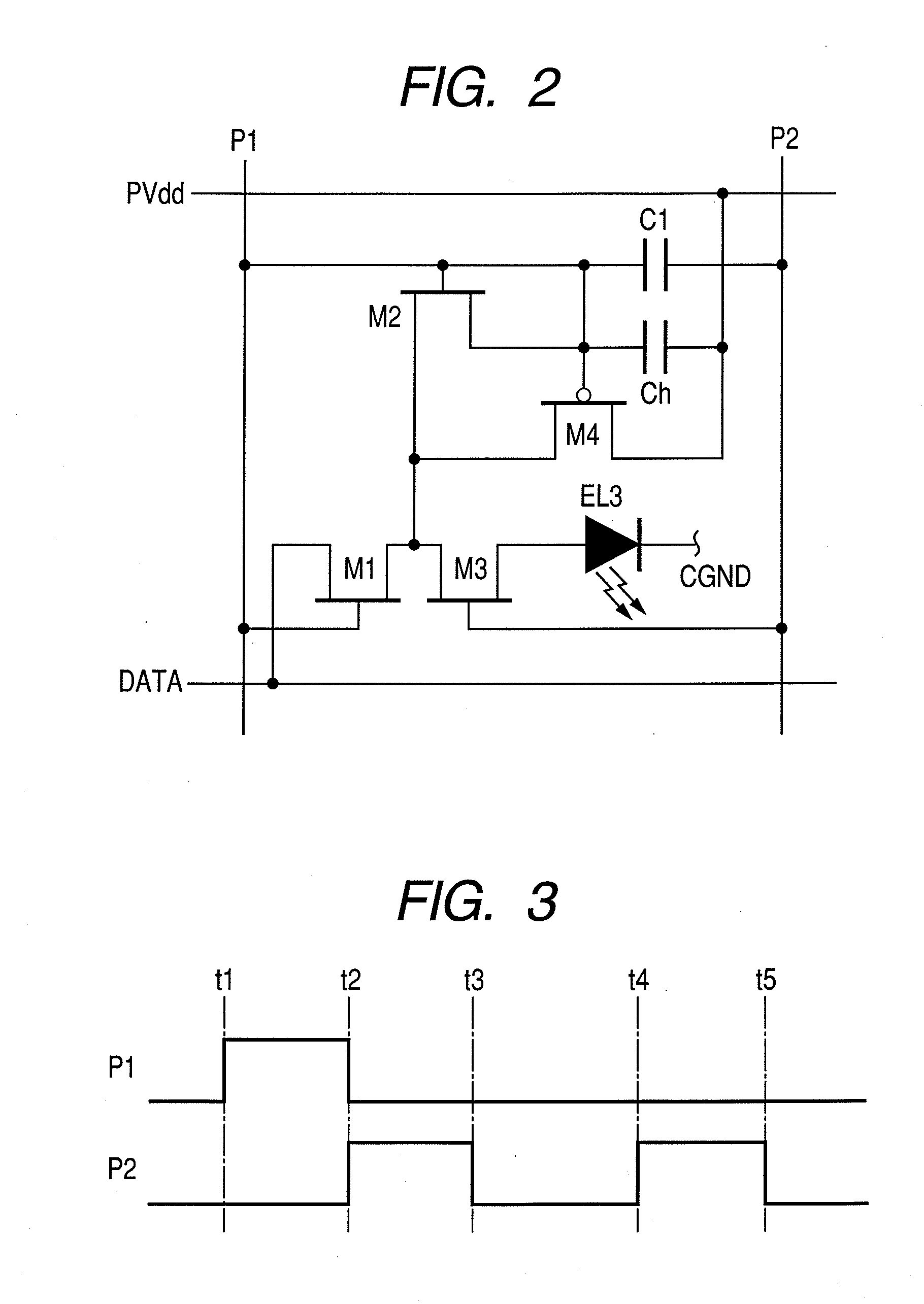
The present invention aims to provide a display apparatus that prevents aberration of white balance in low-brightness display caused by differences in input current among EL devices of different colors. The invention includes a display apparatus with plural light emitting devices arranged in a row and a column direction, each emitting light of a different color. The display apparatus also includes a driving circuit connected to each light emitting device, a scanning line for supplying a selection signal to select the driving circuits, a light emission control line for supplying a light emission control signal, and a data line for supplying a current signal designating brightness of the light emitting device to the selected driving circuits. The driving circuit includes a driving transistor, a first switch, a second switch, a first capacitor, and a second capacitor. The capacitance ratio of the second capacitor to the first capacitor varies according to the color of the light emitting device to which the driving circuit is connected. The invention simplifies the constitution of the circuit for generating the signal current and allows for larger current without error even at low brightness. The invention achieves the white balance irrespective of brightness.

Problems solved by technology

In the current writing type driving circuit, there is a problem that, since a convergence of a signal current flowing in the driving transistor is late when a small current corresponding to low brightness is written, the flowing signal current does not converge on an aimed writing current value during a given writing period.
This is the above-described problem that the convergence of the turn-on current of the driving transistor deteriorates.
Consequently, since R, G and B are unbalanced in dark gray display, the emitted light becomes colored visually.
In any case, in the current writing method, if an accidental error occurs between the white balance in the high-brightness white display and the white balance in the low-brightness white (gray) display, displayed image quality deteriorates.

Method used


Image

  • Display apparatus and driving method thereof
  • Display apparatus and driving method thereof
  • Display apparatus and driving method thereof

Examples


Embodiment Construction

[0044]Hereinafter, the exemplary embodiments of the present invention will be described in detail with reference to the attached drawings.

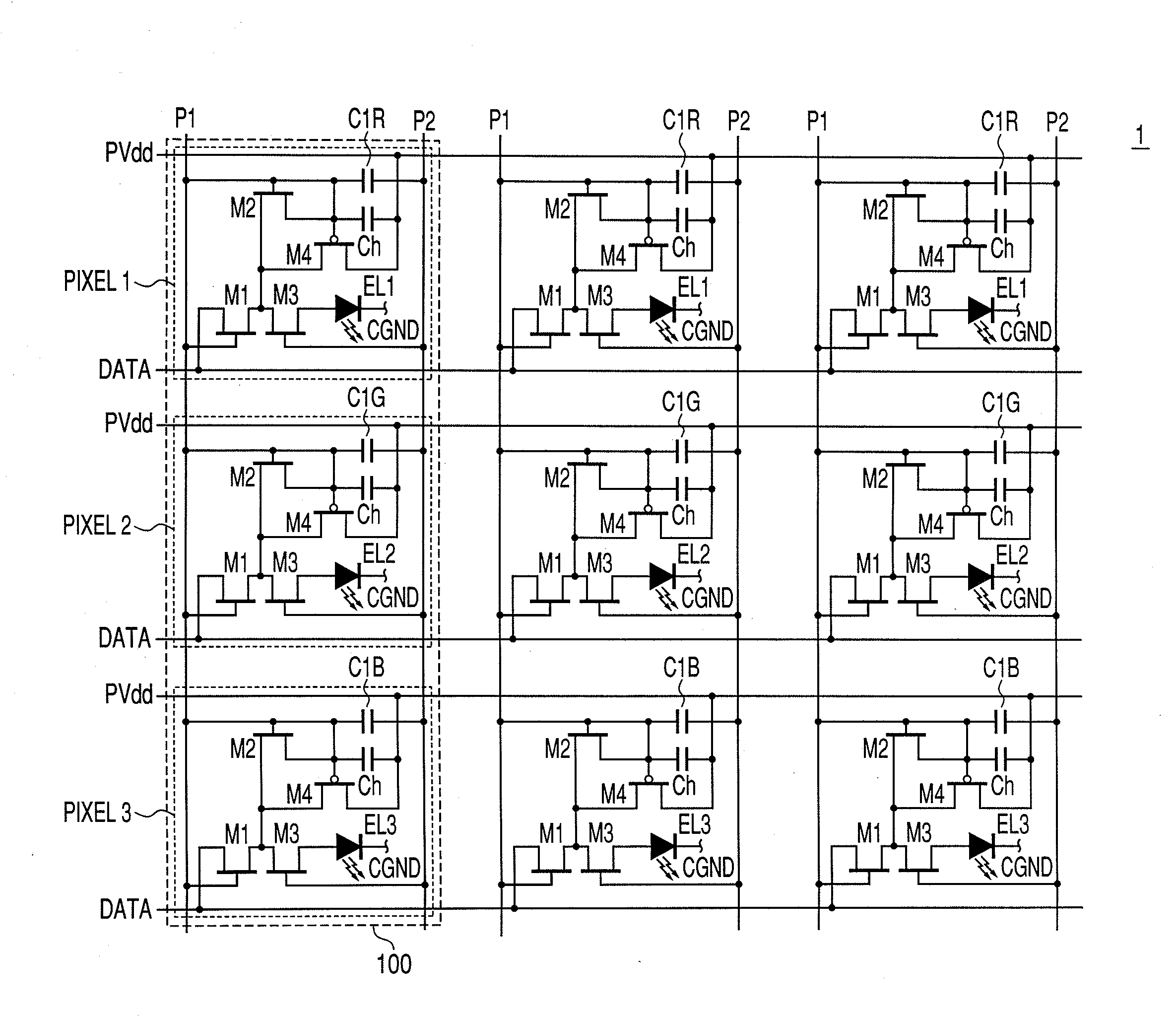
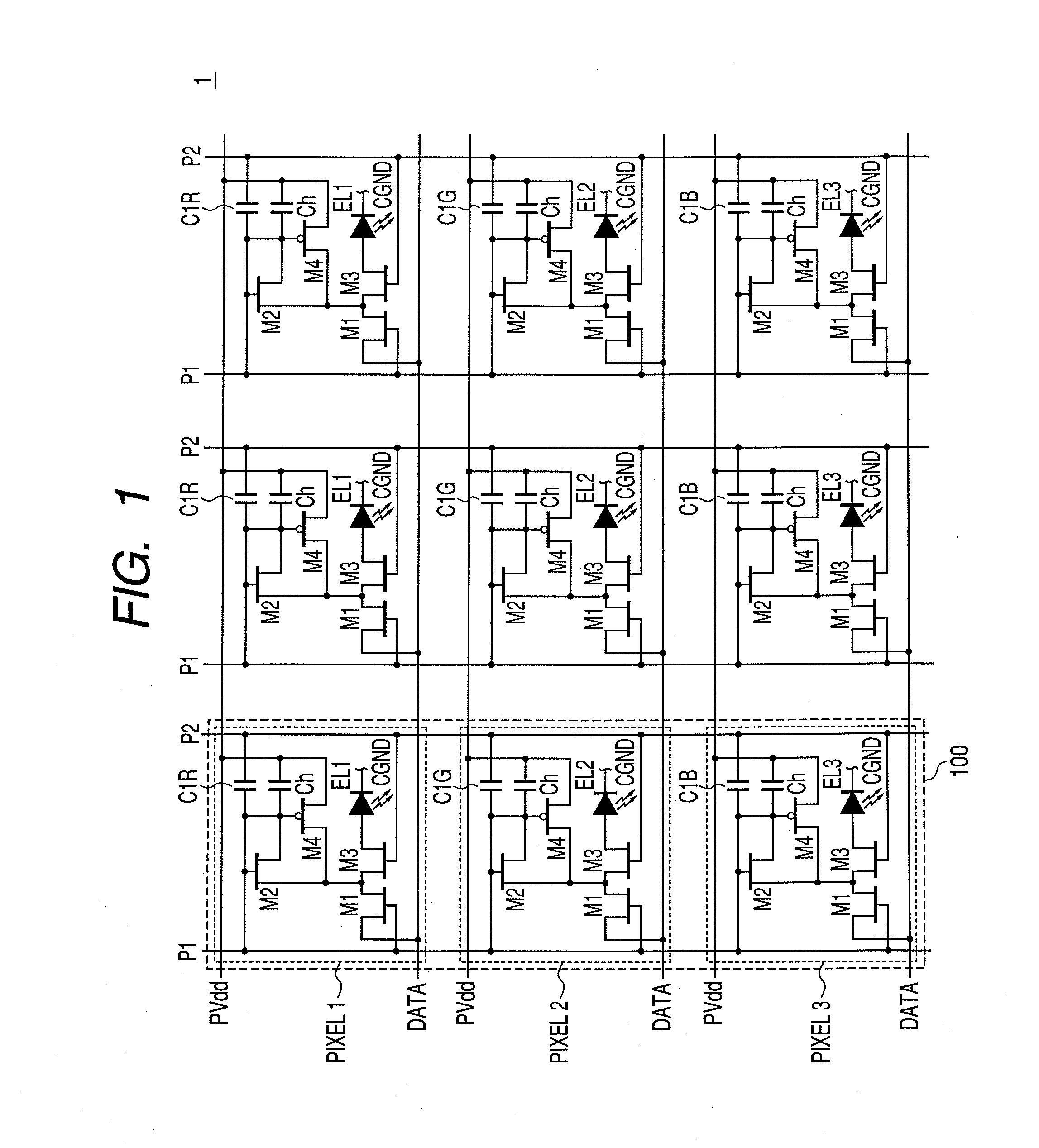
[0045]FIG. 1 is a diagram illustrating a part of the display apparatus according to the present invention.

[0046]In FIG. 1, a display apparatus 1 contains the displaying section on which plural pixels 100 are arranged like a matrix in a row direction (i.e., a vertical direction) and a column direction (i.e., a horizontal direction). Each pixel 100 includes plural light emitting devices which respectively emit light of different colors. In the following description, the light emitting element is assumed to be an EL device, and the different colors are assumed to be red (R), green (G) and blue (B) three colors.

[0047]The pixel 100 is constituted by a sub-pixel PIXEL1 which consists of an EL device EL1 for emitting red (R) light and the driving circuit for driving the EL device EL1, a sub-pixel PIXEL2 which consists of an EL device EL2 for emitting gre...


PUM


Abstract

A display apparatus comprises: plural light emitting devices emitting light by plural kinds of colors; a driving circuit for each light emitting device; a scanning line selecting the driving circuit; a light emission control line causing the light emitting devices to emit light; and a data line supplying to the selected driving circuit a current signal according to brightness, wherein the driving circuit comprises a driving transistor supplying a current, a first-switch between a gate of the driving transistor and the data line, a second-switch between a drain of the driving transistor and the light emitting device, a first-capacitor having one end connected to the gate of the driving transistor and the other end potential-fixed, and a second-capacitor connected to the gate of the driving transistor and the light emission control line, and a capacitance ratio of the second-capacitor to first-capacitor varies according to the color of the emitted light.

Description

BACKGROUND OF THE INVENTION[0001]1. Field of the Invention[0002]The present invention relates to a display apparatus in which an electroluminescence device (called an EL device, hereinafter) or the like for emitting light if a current is input is used for an image displaying operation, and a driving method for the display apparatus.[0003]1. Description of the Related Art[0004]U.S. Pat. No. 6,373,454 discloses that a driving circuit which is provided for EL devices of each pixel, and includes a driving transistor of an active matrix display apparatus of controlling light mission of each pixel by using a data line corresponding to a displaying pixel column and a scanning line corresponding to a displaying pixel row. Further, in this patent document, a current writing type driving circuit for reducing variations in thin film transistor characteristics generally used in driving circuits is proposed.[0005]In the current writing type driving circuit, there is a problem that, since a conve...

Claims


Application Information

Patent Timeline
Patent Type & Authority Applications(United States)
IPC IPC(8): G09G3/30H05B44/00
CPCG09G3/3233G09G2300/0852G09G3/30H01L27/3265H01L27/3211H10K59/35H10K59/1216
Inventor KAWASAKI, SOMEI
Owner CANON KK
Learn More