Radar guided vision system for vehicle validation and vehicle motion characterization

a technology of guided vision and vehicle validation, applied in the field of vision systems, can solve the problems of host vehicle executing hard braking, acc and fcw systems showing poor performance, and undesirable for a host vehicle to brake quickly and hard

Inactive Publication Date: 2009-03-12
SRI INTERNATIONAL +1
View PDF12 Cites 87 Cited by
  • Summary
  • Abstract
  • Description
  • Claims
  • Application Information

AI Technical Summary

Problems solved by technology

Unfortunately, the target vehicle may slow down before changing lanes, causing the host vehicle to brake quickly and hard.
Unfortunately, ACC and FCW systems exhibit poor performance when reacting to drivable stationary objects or objects that are leaving the lane of a host vehicle.
Also, it is undesirable for a host vehicle to execute hard braking when the target vehicle decelerates before leaving the same lane.
An unacceptably high rate of false and nuisance alarms can cause the driver to turn the system off or just ignore the system warning because of lack of trust in system performance.
The main source of false alarms is high objects such as overpasses, road signs, traffic lights, and hanging telephone lines.
However, the system of Broggi and Cerri does not update changes in the geometry of the moving target vehicle, but instead relies solely on pre-calibrated imaging geometry, which leads to inaccuracies, and further, road roughness may cause the failure of target mapping.

Method used


Image

  • Radar guided vision system for vehicle validation and vehicle motion characterization
  • Radar guided vision system for vehicle validation and vehicle motion characterization
  • Radar guided vision system for vehicle validation and vehicle motion characterization

Examples


Embodiment Construction

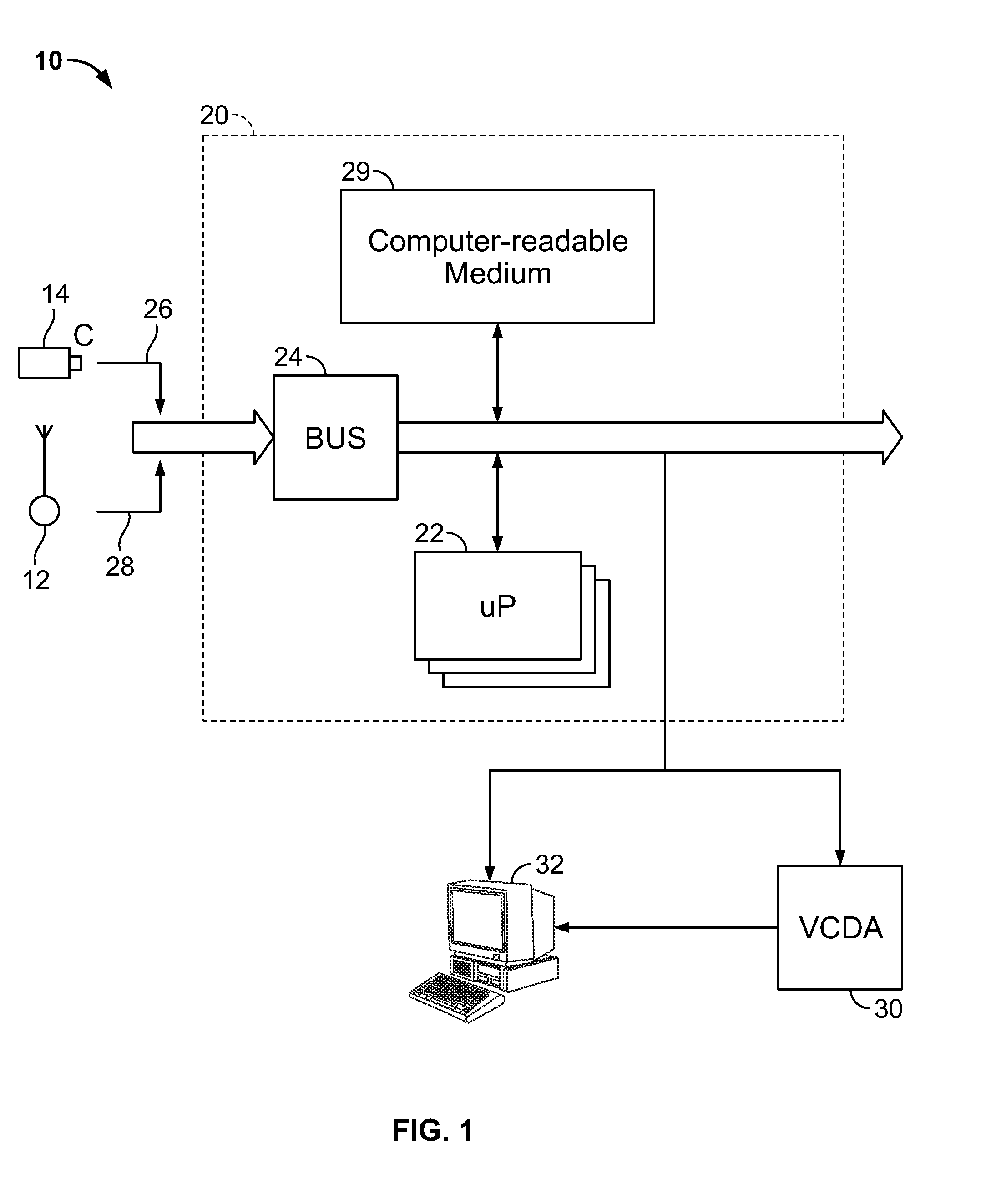
[0033]Referring now to FIG. 1, there is shown a radar-guided vision system 10, constructed according to an embodiment of the present invention. By way of a non-limiting example, the system 10 receives radar data from a radar system 12 and video from a camera 14, respectively. The camera 14 can be, for example, a digital camera such as a Guppy camera with a 640×480 CCD sensor and a 25 degree FOV lens. The system 10 can also include a computing platform 20. The computing platform 20 may include an embedded system (e.g., an Intel platform with DUO (1.83 Ghz) processor) comprising one or more processors 22 which includes a bus system 24 (e.g., an on board CAN bus system) which is fed by a video data stream 26 and a radar data stream 28 via the one or more processors 22 or directly to a computer-readable medium 29. The computer readable medium 28 can also be used for storing the instructions of the system 10 to be executed by the one or more processors 22, including an operating system, ...


PUM


Abstract

A method for determining whether a target vehicle in front of a host vehicle intends to change lanes using radar data and image data is disclosed, comprising the steps of processing the image data to detect the boundaries of the lane of the host vehicle; estimating a ground plane by determining a projected vanishing point of the detected lane boundaries; using a camera projection matrix to map the target vehicle from the radar data to image coordinates; and determining lane change intentions of the target vehicle based on a moving trajectory and an appearance change of the target vehicle. Determining lane change intentions based on a moving trajectory of the target vehicle is based on vehicle motion trajectory relative to the center of the lane such that the relative distance of the target vehicle from the center of the lane follows a predetermined trend. Determining lane change intentions based on an appearance change of the target vehicle is based on a template that tracks changes to the appearance of the rear part of the target vehicle due to rotation.

Description

CROSS-REFERENCE TO RELATED APPLICATIONS[0001]This application claims the benefit of U.S. provisional patent application No. 60 / 970,618 filed Sep. 7, 2007, the disclosure of which is incorporated herein by reference in its entirety.GOVERNMENT RIGHTS IN THIS INVENTION[0002]This invention was made with U.S. government support under contract number ABGP006070035. The U.S. government has certain rights in this invention.FIELD OF THE INVENTION[0003]The present invention relates generally to vision systems, and more particularly, to a radar guided vision system and method for detecting the presence of a target vehicle in front of a host vehicle in the same lane of traffic and for determining whether the target vehicle intends to change lanes.BACKGROUND OF THE INVENTION[0004]When there is a vehicle on a highway in front of a host (i.e. following) vehicle, it is desirable for the driver of the host vehicle to know the intensions of the driver of the in-front (i.e. the target) vehicle as to w...

Claims


Application Information

Patent Timeline
Patent Type & Authority Applications(United States)
IPC IPC(8): G06K9/00
CPCG06K9/00798G01S13/867G01S2013/93271G06V20/588G01S13/931
Inventor TAN, YIHAN, FENGELEDATH, JAYANKUMAR, RAKESH
Owner SRI INTERNATIONAL
Why Eureka
Try Eureka