Device and method for measuring and machining spectacle lens, spectacle lens manufacturing method, and spectacles manufacturing method

Inactive Publication Date: 2009-03-12
HOYA CORP
View PDF2 Cites 22 Cited by
  • Summary
  • Abstract
  • Description
  • Claims
  • Application Information

AI Technical Summary

Benefits of technology

[0030]According to the present invention, obtained is an effect of being capable of installing the spectacle lens components on the spectacle lens with a requested strength because the mounting part can b...

Problems solved by technology

However, it happens sometimes that a spectacle lens manufactured by edging is completed as if a pos...

Method used


Image

  • Device and method for measuring and machining spectacle lens, spectacle lens manufacturing method, and spectacles manufacturing method
  • Device and method for measuring and machining spectacle lens, spectacle lens manufacturing method, and spectacles manufacturing method
  • Device and method for measuring and machining spectacle lens, spectacle lens manufacturing method, and spectacles manufacturing method

Examples


Embodiment Construction

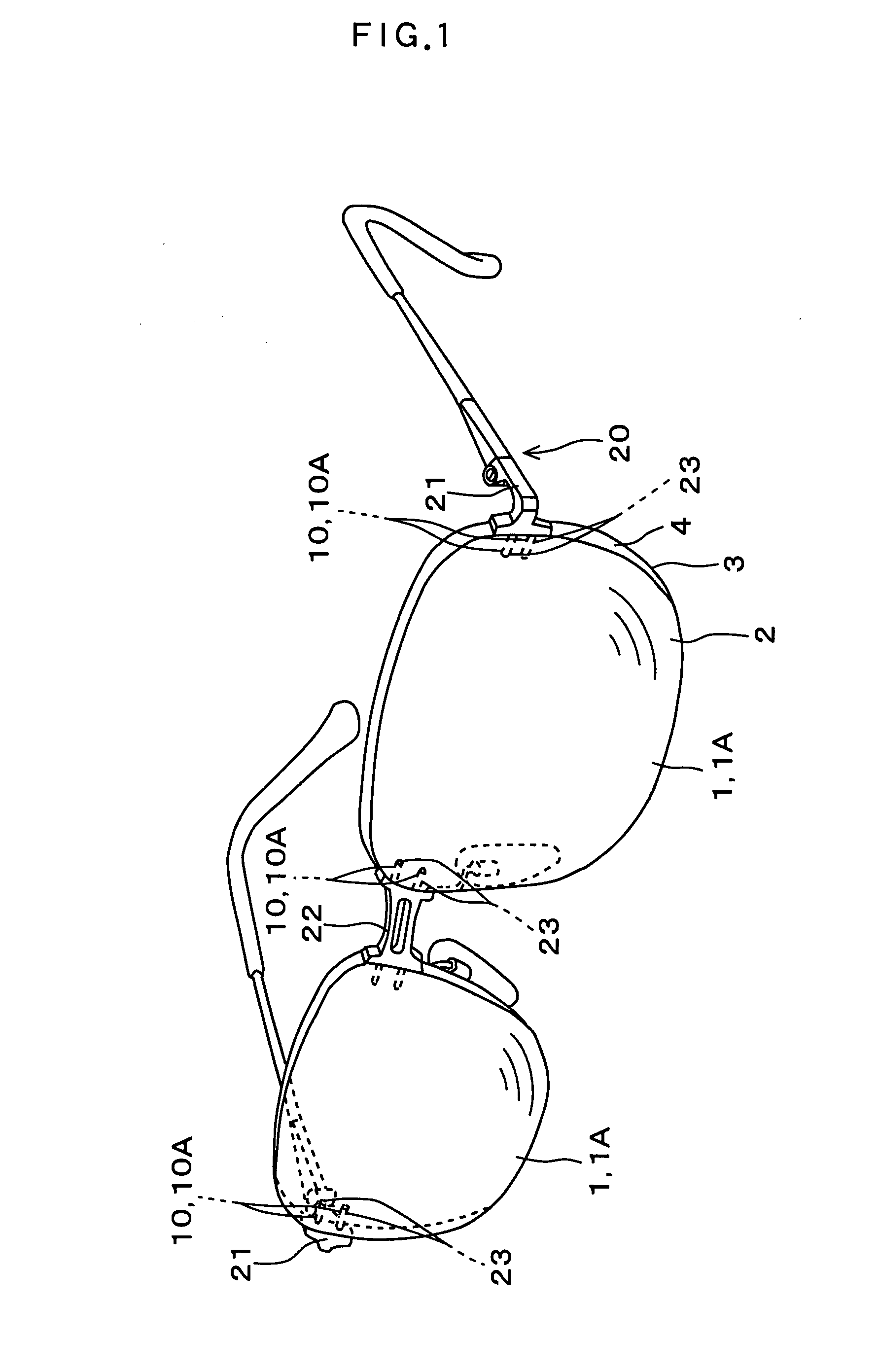
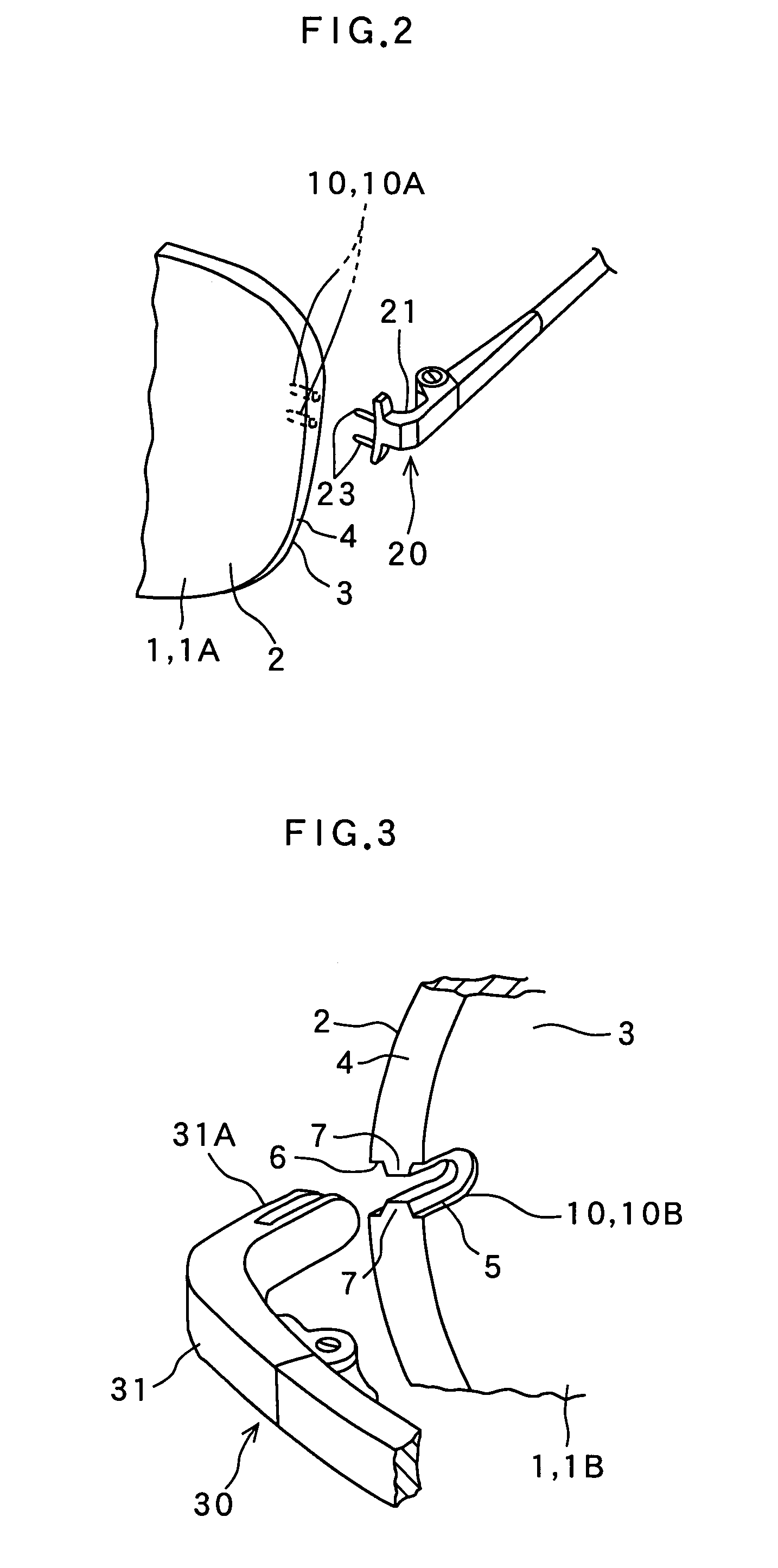
[0076]Embodiments for performing the present invention will be explained based on the drawings below. FIGS. 1, 2, and 3 show a plastic spectacle lens 1, in which a mounting part 10 is machined by a spectacle lens measuring and machining device relating to the present embodiment. The spectacle lens 1 is a meniscus lens, in which one optical surface is a convex face 2 and the other optical surface is a concave face 3, and the edge face 4 of the spectacle lens 1 is edged by an edging device which will be described later, which ensure that the spectacle lens 1 is of the specified lens shape.

[0077]There are a spectacle lens 1A shown in FIG. 2 and a spectacle lens 1B shown in FIG. 3 in the spectacle lens 1. The mounting part 10 of the spectacle lens 1A in FIG. 2 is a closed-end hole 10A extending from the edge face 4 of the spectacle lens 1A toward the inside of the lens within the lens thickness range, and the mounting part 10 in FIG. 3 is a notched part 10B extending from the edge face ...


PUM

PropertyMeasurementUnit
Thicknessaaaaaaaaaa
Heightaaaaaaaaaa
Distanceaaaaaaaaaa

Abstract

A mounting part for mounting spectacle frame components such as lugs can be machined after confirming that a lens thickness at a mounting part-machined portion where the mounting part is machined is equal to or larger than the specified value, and can be installed the spectacle lens components on the spectacle lens with a requested strength. The device, the method for the above, a spectacle lens manufacturing method, and a spectacles manufacturing method are given. The spectacle lens (1) is fed to a lens thickness measuring device (70) by a lens feeder. The fed amount of the spectacle lens in this feeding is based on the measured results of a distance between a frame center forming a block center by a lens holder in an edging for manufacturing the spectacle lens (1) from a raw material lens and the edge face of the spectacle lens (1) where the mounting part is to be machined. The thickness of the lens at the mounting part-machined portion can be accurately measured by the measuring device (70) even if an error produced in the edging is included in the distance.

Description

TECHNICAL FIELD[0001]The present invention relates to a measuring and machining device used for machining a mounting part for mounting spectacle frame components such as lugs to a spectacle lens, a method of measuring and machining thereof, and a spectacle lens manufacturing method and a spectacles manufacturing method using the measuring and machining method, and is applicable to a spectacle lens to be mounted to a rimless spectacle frame.BACKGROUND ART[0002]Regarding a plastic spectacle lens to be installed in a spectacle frame, when a lens blank manufactured by a casting method or the like has a surface not to be optically finished, various surface treatment are performed after this surface is optically finished by cutting and polishing, and the lens is manufactured by edging the lens thus obtained to the specified lens shape requested by a spectacle wearer. Note that a lens before edging is expressed as a “raw material lens” in this specification and an edging-processed lens is ...

Claims


Application Information

Patent Timeline
IPC IPC(8): B23B51/08G01B5/00G01B5/06G01B5/14G02C13/00
CPCB24B9/14B24B49/00G01B5/06G01B5/20Y10T29/49771G02C13/001Y10T408/34Y10T408/03G02C1/02
Inventor ARAI, MICHIONISHIOKA, MASASHI
Owner HOYA CORP
Why Eureka
Try Eureka