Spinal needle optical sensor

a technology of optical sensor and spinal needle, which is applied in the field of medical sensors, can solve the problems of prohibitively expensive general use, difficult to perform lumbar punctures in the conventional manner, and substantial patient discomfort, and achieve the effects of reducing patient discomfort, reducing the number of traumatic spinal taps, and guiding accurately

Inactive Publication Date: 2009-03-12
CHARLES STARK DRAPER LABORATORY
View PDF9 Cites 24 Cited by
  • Summary
  • Abstract
  • Description
  • Claims
  • Application Information

AI Technical Summary

Benefits of technology

[0008]The inventors have realized that by incorporating a spinal needle with an optical sensor (e.g. an optical tomographic system) capable of sensing the region located in front of the needle tip, a user may more easily and accurately guide the spinal needle to its desired location. For example, some embodiments permit doctors to sense the region in front of the needle tip (e.g. with >1 mm of axial visibility) and determine whether the needle is being directed toward bone (vertebrae) or the dura (the desired region). Such a device and technique helps doctors decrease the number of traumatic spinal taps (also referred to as lumbar punctures), reduces patient discomfort, and allows successful procedures under less than ideal conditions.

Problems solved by technology

Even under good conditions, techniques of the type described above may require repeated insertions and retractions of the spinal needle, and may result in repeated contact of the needle tip with bone, leading to substantial patient discomfort.
A variety of conditions, including marked obesity, degenerative disease of the spine, previous spinal surgery, recent lumbar puncture, and dehydration, can make it difficult to perform lumbar punctures in the conventional manner.
Video fluoroscopy requires a radiologist and a technologist to perform the procedure, thus making it prohibitively expensive for general use.

Method used


Image

  • Spinal needle optical sensor
  • Spinal needle optical sensor
  • Spinal needle optical sensor

Examples


Embodiment Construction

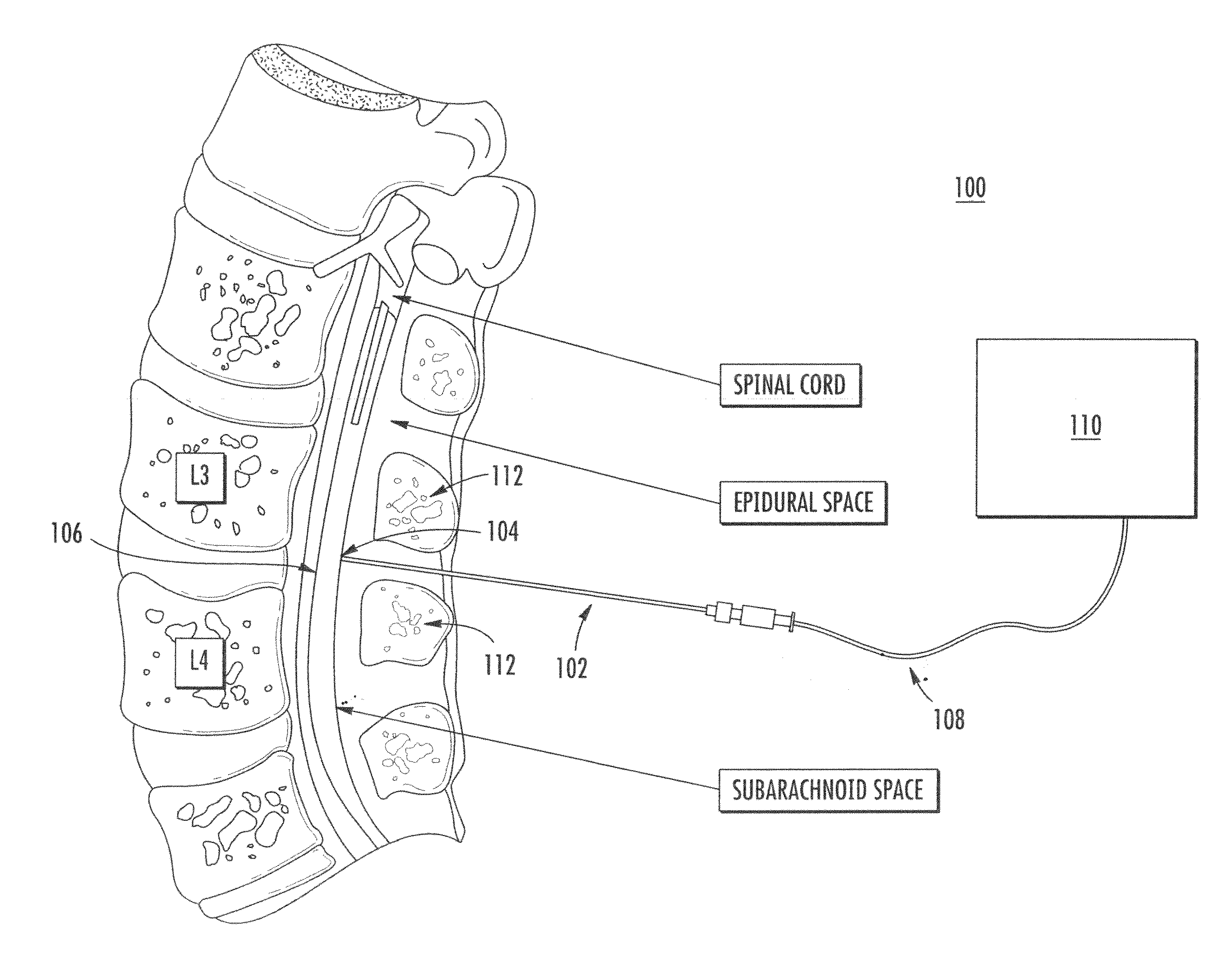
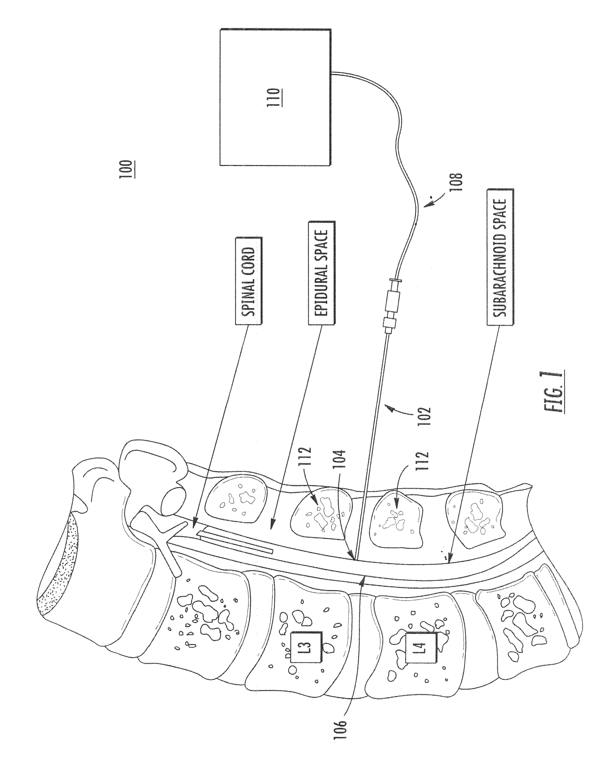
[0042]Referring to FIG. 1, spinal needle sensor 100 includes spinal needle 102. As shown, spinal needle 102 may be inserted through a patient's back, and needle tip 104 directed to a desired position, e.g., the spinal dura 106. Optical fiber 108 connects needle 102 to optical coherence tomographic (OCT) system 110. As described in detail herein, OCT system 110 optically senses the region in front of needle tip 104. This allows a user to more accurately insert needle 102 and position needle tip 104 in a desired position. For example, information provided by OCT system 110 may be used during insertion of needle 102 to avoid contact of needle tip 104 with areas of bone tissue 112.

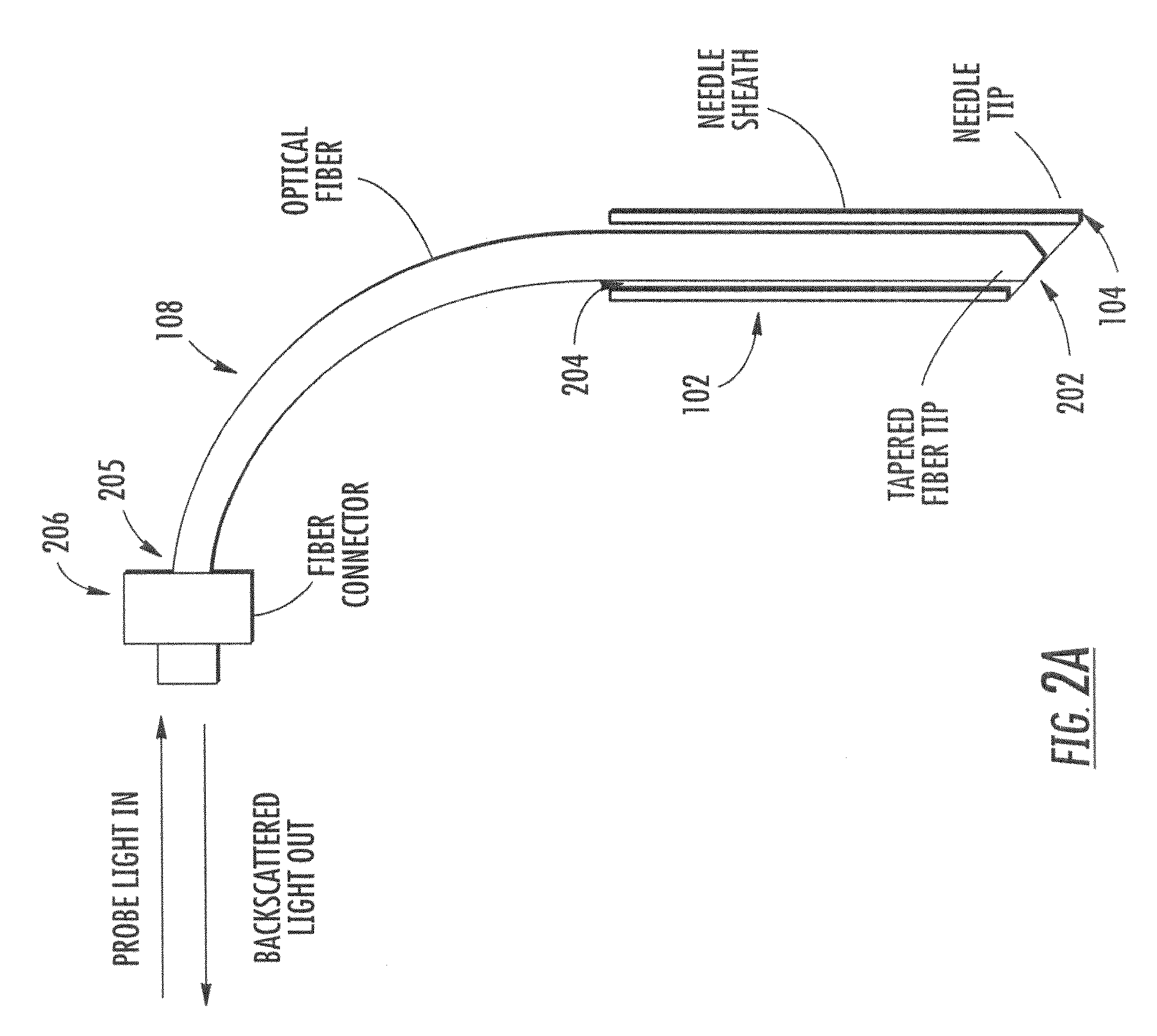
[0043]Referring to FIG. 2A, a single optical fiber 108 is used to transport the probe light from OCT system 110 (not shown) to needle tip 104 and then transport the light backscattered from tissue in front of needle tip 104 to the OCT system 110. Spinal needle 102 has a hollow cavity 204. Fiber 108 extends thr...


PUM


Abstract

An apparatus is disclosed including: an optical coherence tomographic system; a spinal needle having a needle tip adapted to penetrate tissue; and an optical delivery system adapted to direct probe light from the optical coherence tomographic system onto tissue located in front of the needle tip, collect test light backscattered from the tissue, and transmit the test light to the optical coherence tomographic system. The optical coherence tomographic system is adapted to provide information indicative of one or more properties of the tissue based on the test light.

Description

CROSS-REFERENCE TO RELATED PATENT APPLICATIONS[0001]The present application claims benefit of U.S. Provisional Application Ser. No. 60 / 895,252 filed Mar. 16, 2007, the contents of which are incorporated by reference herein in their entirety.BACKGROUND[0002]The present disclosure relates to medical sensors, for example, optical medical sensors.[0003]Physicians use spinal needles for diagnostic, anesthetic, therapeutic and other procedures including, for example, lumbar punctures, spinal taps, and epidurals. For example, in a typical procedure a lumbar puncture is performed by inserting a needle in a patient's back, for example, at, or one space above or below, the L4-5 interspace. At this level, the dural sac contains cerebrospinal fluid and exiting nerve roots in the form of the cauda equina. In normal adults, the spinal cord itself has terminated at approximately at the tenth or eleventh thoracic vertebra. This is fortunate, since it keeps the spinal cord far from potential injury ...

Claims


Application Information

Patent Timeline
Patent Type & Authority Applications(United States)
IPC IPC(8): A61B5/05
CPCA61B5/0066A61B5/4504A61B5/6852A61B2562/228A61B2017/00057A61B2019/462A61B17/3401A61B5/407A61B2090/062
Inventor TAPALIAN, H. CHARLESROGOMENTICH, FRANCIS J.WEINBERG, MARC STEVEN
Owner CHARLES STARK DRAPER LABORATORY
Why Eureka
Try Eureka