Intramedullary Nail Distal Targeting Device

Inactive Publication Date: 2009-03-12
ORTHOPAEDIC INT
View PDF17 Cites 63 Cited by
  • Summary
  • Abstract
  • Description
  • Claims
  • Application Information

AI Technical Summary

Benefits of technology

[0006]The present invention aims to solve the aforementioned problems of the prior art by providing an intramedullary nail distal targeting device that can accurately locate the distal screw holes in an intramedullary nail inserted into a fractured bone with the use of a fluoroscope. Moreover, the herein proposed targeting device of the present invention is provided with novel features that can immediately and accurately correct the alignment of a drill in case the same misses the screw hole of the intramedullary nail during surgery.

Problems solved by technology

The problem with these systems is that since there is no guarantee that the nail will not bend during insertion, there is always a possibility of misalignment between the distal screw hole and the drill-guiding hole, even assuming perfect alignment between the distal screw hole and the drill-guiding hole prior to nail insertion.

Method used


Image

  • Intramedullary Nail Distal Targeting Device
  • Intramedullary Nail Distal Targeting Device
  • Intramedullary Nail Distal Targeting Device

Examples


Embodiment Construction

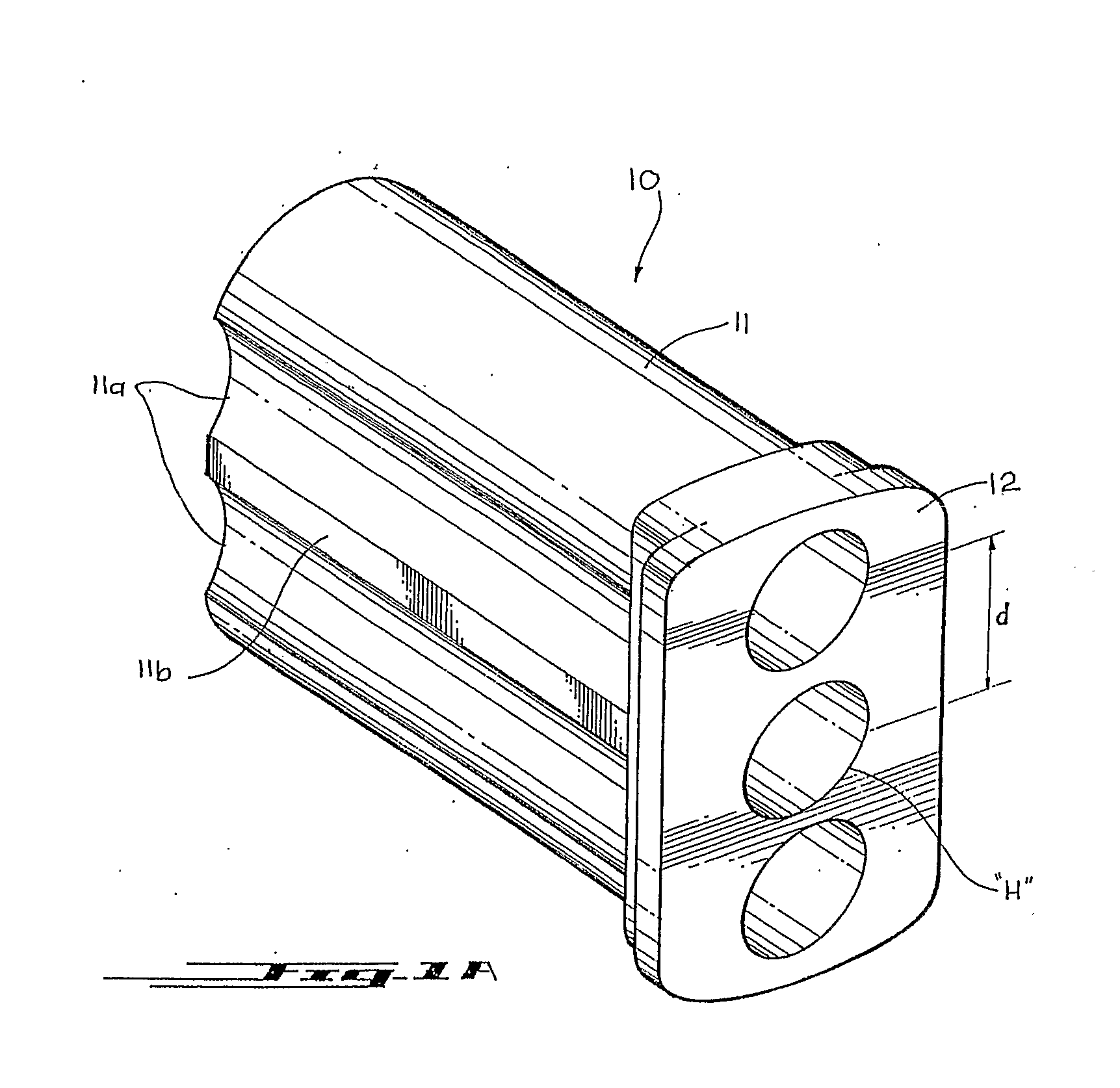
[0019]Referring now to the different views of the drawings, there is shown an intramedullary nail distal targeting device and a guide sleeve therefor designated as 10.

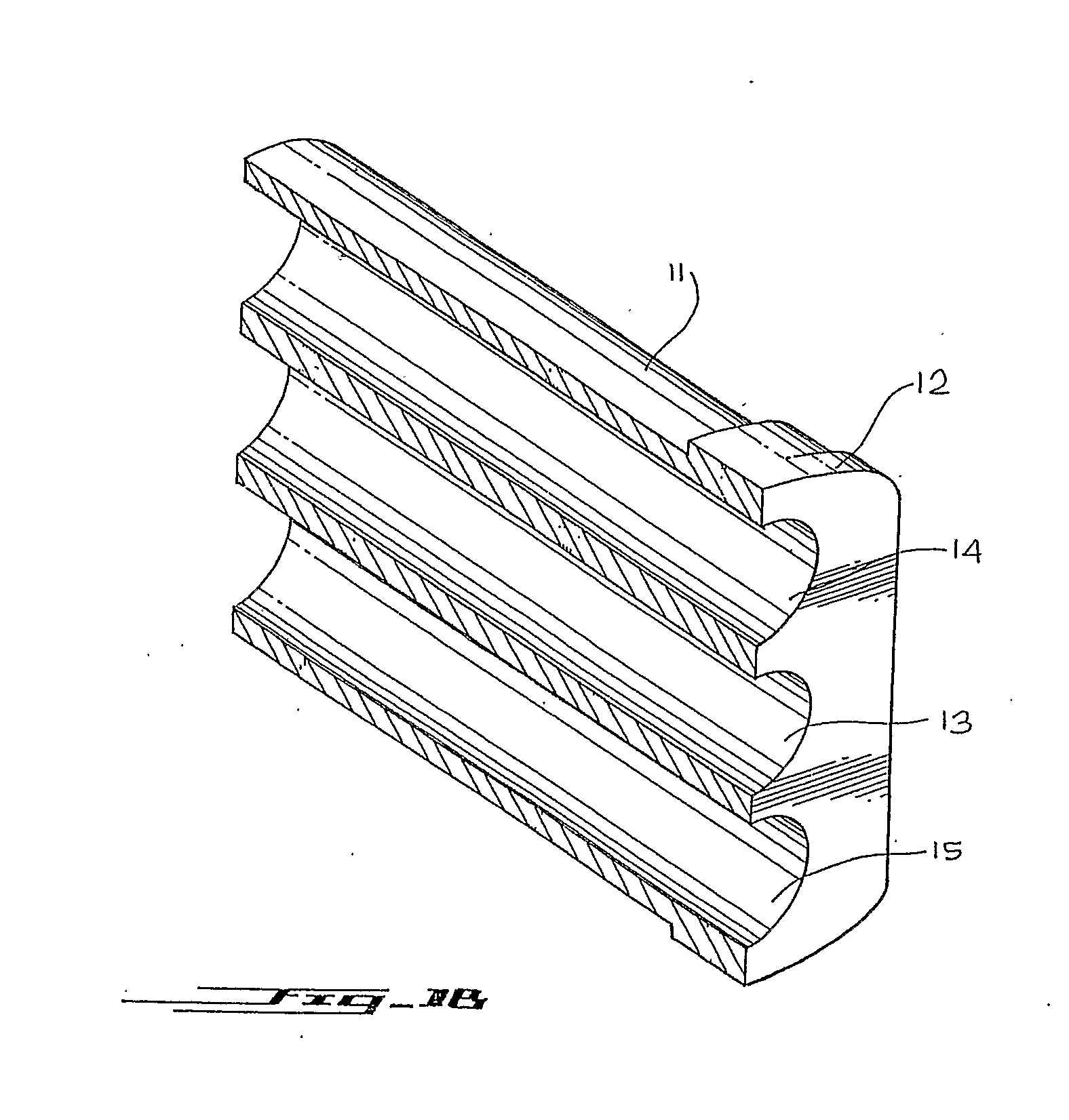
[0020]As shown FIGS. 1A and 1B, drill sleeve 10 comprises of a main tubular body 11 having a sleeve holder 12 being disposed on one end portion thereof, said tubular body having at least a pair of opposed scalloped side portions 11a defining interlocking surfaces 11b therebetween, and a plurality of spaced apart and aligned drill-guiding means “H” extending between the opposed end portions of the tubular body 11. As further shown in FIG. 1B, drill-guiding hole means “H” comprise of a central drill-guiding hole 13, and a pair of opposed anterior and posterior drill-guiding holes 14 and 15 being disposed adjacently with respect to the central drill-guiding hole 13.

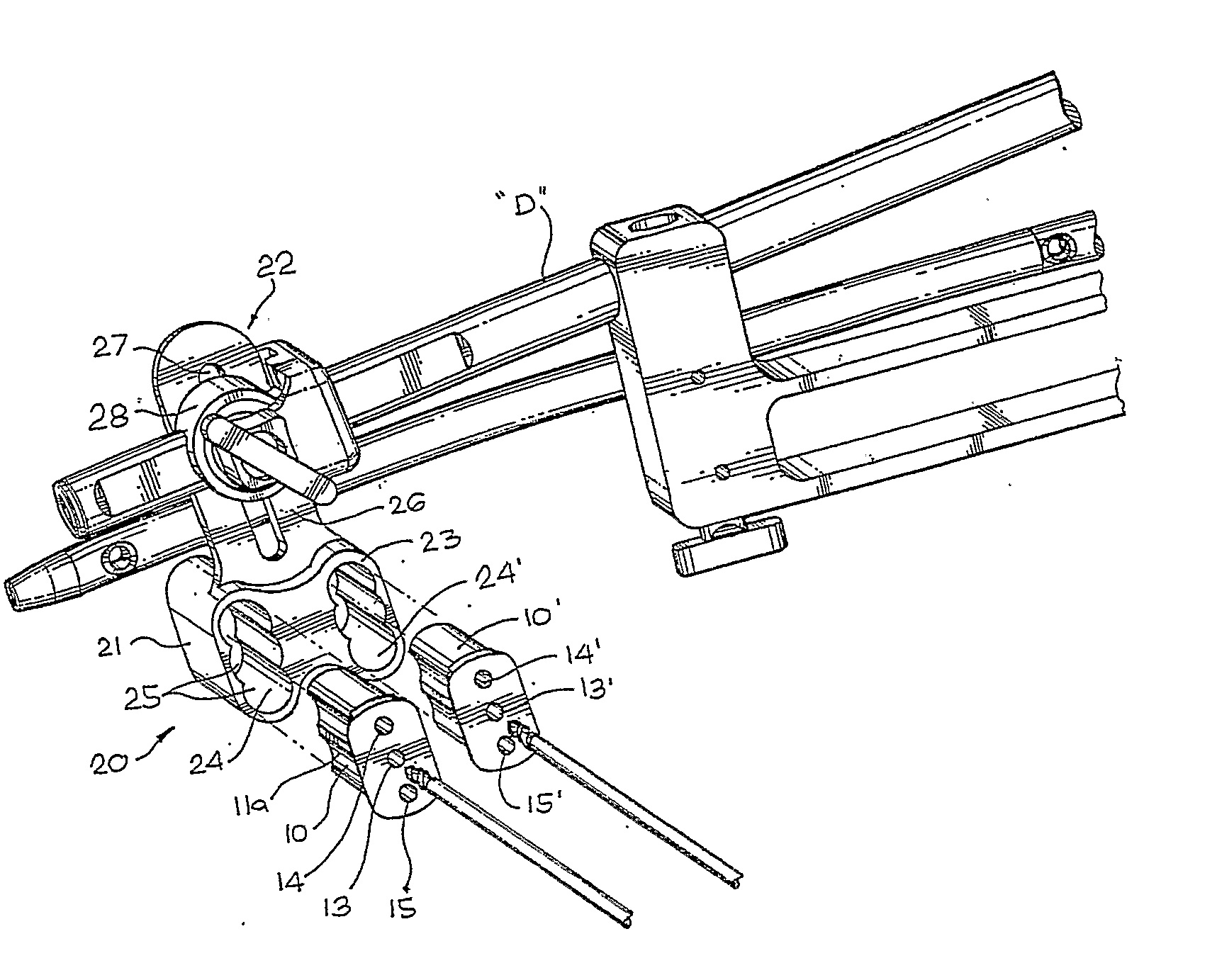
[0021]FIGS. 2 to 6 show the preferred embodiment of the present invention for an intramedullary nail distal targeting device 20 adapted to be installed to an e...


PUM


Abstract

The present invention relates to an intramedullary nail distal targeting device (20) adapted to be installed to an external jig system (A) having a proximal attachment (B) to support an intramedullary nail (C) thereon and an extension arm (D) secured to the proximal attachment (B), the nail distal targeting device including a drill guide (21) being defined by an abbreviated cylindrical body (23) having at least a pair of guide slots (24, 24′) each of the guide slots (24, 24′) having a scalloped inner surface (25), an attaching mechanism (22) being provided at the upper portion of the drill guide (21), the attaching mechanism (22) secured in a rotating and sliding manner to a distal end of the extension arm (D) and at least a pair of guide sleeves (10, 10′) being telescopically fitted correspondingly into the slots (24, 24′) of the drill guide (21), each of the guide sleeves (10, 10′) having a scalloped outer surface to correspondingly fit into the guide slots (24, 24′), each of the guide sleeves (10, 10′) being provided with aligned and spaced apart drill-guiding holes (13, 14, 15) extended between the opposed end portions thereof.

Description

FIELD OF THE INVENTION[0001]The present invention relates in general to external targeting jig systems, but more particularly to an external jig system that uses a drill guide device connected to the proximal end of an intramedullary nail through a series of attachments. The herein proposed device of the present invention is used for effectively locating the distal screw holes in an intramedullary nail inserted into a fractured bone, without the use of a fluoroscope.BACKGROUND OF THE INVENTION[0002]It is known to those skilled in the art that an intramedullary nail has a general tendency to bend in the anterior-posterior direction during insertion into the bone, particularly in the femur. The anterior-posterior direction is perpendicular to the screw hole axis, and thus significantly affects the alignment between the drill-guiding hole in the drill guide and the nail screw hole. Medial-lateral bending on the other hand does not significantly affect drill-guiding alignment with the s...

Claims


Application Information

Patent Timeline
IPC IPC(8): A61B17/58
CPCA61B17/1725
Inventor SASING, JUDE L.DAYANGHIRANG, ARISTEDES C.YAP, DENNIS ALPHONSEGUSTILO, RAMON B.CHAN, FRANCIS O.FRESNIDO, ROBERTO R.
Owner ORTHOPAEDIC INT
Why Eureka
Try Eureka