Magnet temperature control device

Inactive Publication Date: 2009-03-19
SIEMENS HEALTHCARE GMBH
View PDF4 Cites 4 Cited by
  • Summary
  • Abstract
  • Description
  • Claims
  • Application Information

AI Technical Summary

Benefits of technology

[0009]An object of the present invention is to provide a magnet temperature control device for keeping the temperature stability of the magnet, and in particular for keeping the temperature stability inside the magnet.
[0016]Compared with the prior art in which a heater is distributed only on the surface of a magnet, in the present invention the pipeline distributed inside the magnet can control the magnet temperature more directly and effectively, so as to smooth and eliminate a temperature change of the magnet promptly the liquid or gas flow therein, thereby making the magnet temperature more stable.

Problems solved by technology

The reason is that the characteristics of the permanent magnet material change considerably with the temperature, thus the magnetic field excited by it has corresponding changes, and such changes are shown as fluctuation in magnetic field density and deterioration in its uniformity, and the abovementioned changes in the magnetic field will directly result in a decrease of imaging quality of the magnetic resonance system.
When heat is generated inside the magnet, by way of adjusting the heater on the surface of the magnet alone it can only ensure the surface temperature of the magnet to be constant, while the temperature change inside the magnet will keep oscillating for quite a long time and it cannot be eliminated, thus resulting in the fluctuation of magnetic density and deterioration of uniformity, and damaging the imaging quality of the magnetic resonance system.

Method used


Image

  • Magnet temperature control device
  • Magnet temperature control device
  • Magnet temperature control device

Examples


Embodiment Construction

[0020]The basic concept of the present invention is to regulate, by a magnet temperature control device, the heat generated inside a magnet per se via a pipeline arranged inside the magnet of a permanent magnet magnetic resonance system, so as to smooth and eliminate a temperature change of the magnet promptly, and to ensure the temperature stability of the magnet.

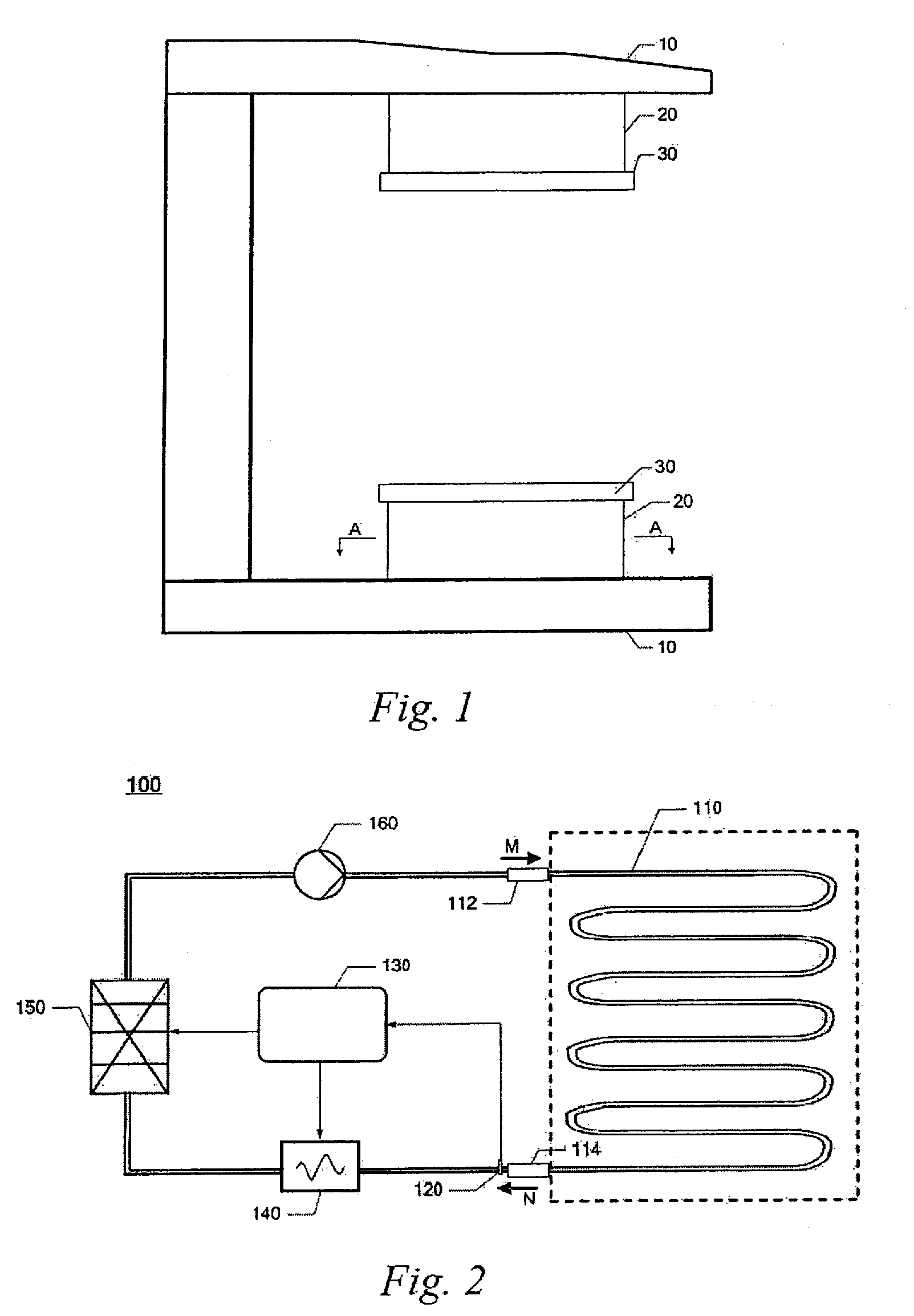
[0021]The magnet temperature control device of the present invention is mainly for applications in permanent magnet magnetic resonance systems. As shown in FIG. 1, said permanent magnet magnetic resonance system comprises upper and lower magnetic yokes 10, and magnets 20 which in turn are arranged respectively on said upper and lower magnetic yokes 10.

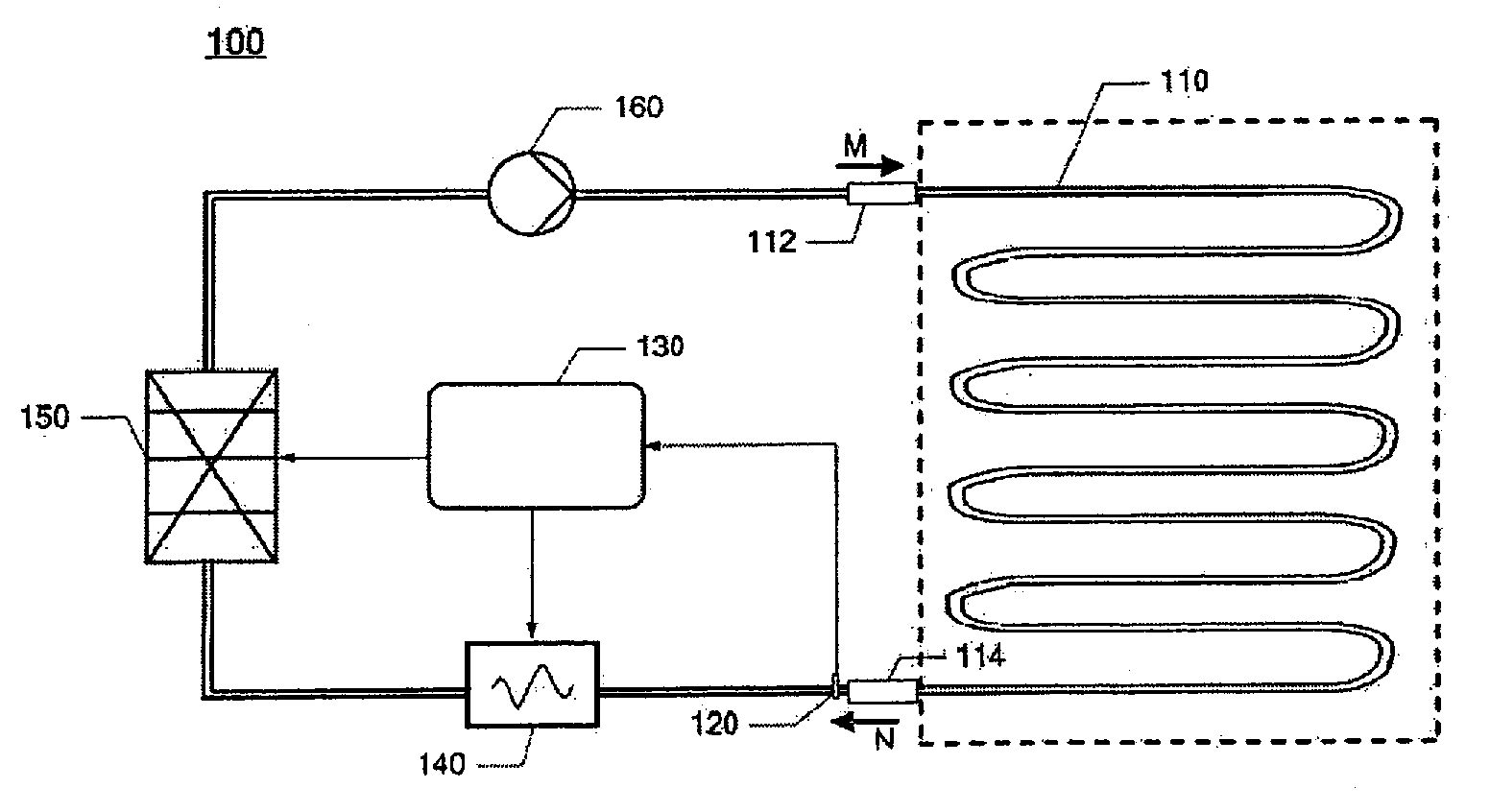
[0022]As shown in FIG. 2, the magnet temperature control device 100 of the present invention has a pipeline 110 and into the pipeline 110 is introduced a circulating liquid or gas flow. A part of said pipeline 110 (the part within the dash line box) is arranged inside said ma...


PUM


Abstract

A magnet temperature control device, for use in a magnetic resonance system having a magnet, includes a pipeline and a temperature regulator. The pipeline is connected to a liquid or gas circulation, and the temperature regulator is connected in series in the pipeline to regulate the temperature of the liquid or gas. A part of the pipeline is arranged inside the magnet, while the rest of the pipeline is arranged outside said magnet; the part of said pipeline which is arranged inside said magnet is distributed uniformly within the magnet, and its cross-sectional shape is in an annular, helical, radicalized or network form, or a combination thereof. Compared to the use of a heater that is distributed only on the surface of the magnet, the pipeline distributed inside the magnet can control the magnet temperature more directly and effectively, so as to smooth and eliminate the temperature change of the magnet promptly by the liquid or gas flow therein, thereby making the magnet temperature more stable.

Description

BACKGROUND OF THE INVENTION[0001]1. Field of the Invention[0002]The present invention relates to a magnet temperature control device, and in particular to a magnet temperature control device for a permanent magnet magnetic resonance system.[0003]2. Description of the Prior Art[0004]Referring to FIG. 1, in a typical permanent magnet magnetic resonance system, magnets 20, pole plates 30 are respectively arranged in turn on upper and lower magnetic yokes 10. Stability is an important parameter for the magnetic field components of a permanent magnet magnetic resonance system, although there exists a plurality of external factors that affect the stability of a permanent magnet, in which the temperature stability is the most important one. However, the magnetic components for permanent magnet magnetic resonance, in particular the magnets 20 for generating the magnetic field are very sensitive to temperature changes. The reason is that the characteristics of the permanent magnet material c...

Claims


Application Information

Patent Timeline
IPC IPC(8): F28D15/00
CPCG01R33/3804G05D23/1919G01R33/383G01R33/3806
Inventor LI, AN FENGLIU, XIAO GUANG
Owner SIEMENS HEALTHCARE GMBH
Why Eureka
Try Eureka