Electric rotating machine

a rotating machine and rotating shaft technology, applied in the direction of synchronous machines, windings, dynamo-electric components, etc., can solve the problem of high manufacturing cost of such machines, and achieve the effect of significantly reducing magnetic noise and low cos

Active Publication Date: 2009-03-19
DENSO CORP
View PDF21 Cites 18 Cited by
  • Summary
  • Abstract
  • Description
  • Claims
  • Application Information

AI Technical Summary

Benefits of technology

[0019]According to the present invention, it is possible to provide an electric rotating machine whose magnetic noise is significantly lowered at low cost.

Problems solved by technology

However, since this structure needs two sets of rectifier devices for converting an AC current induced in the stator into a DC current, the manufacturing cost thereof is high.

Method used


Image

  • Electric rotating machine
  • Electric rotating machine
  • Electric rotating machine

Examples


Embodiment Construction

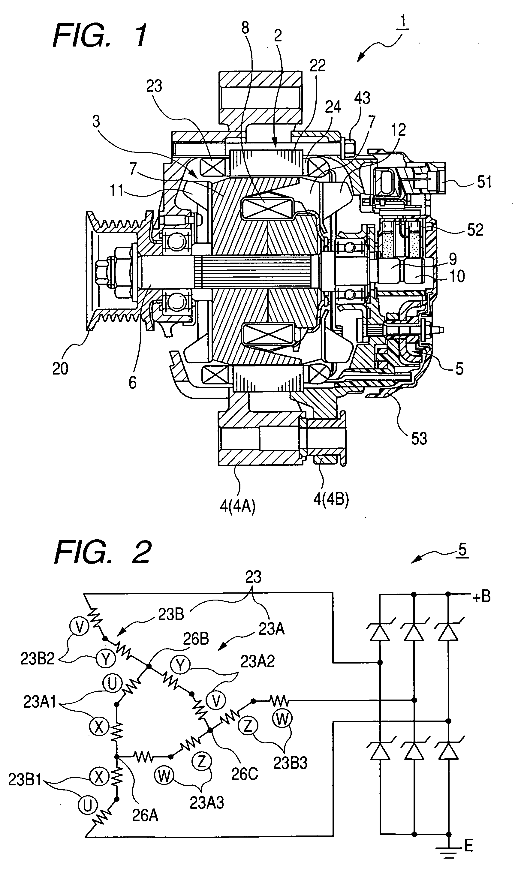
[0032]FIG. 1 is a diagram showing an overall structure of a vehicle-mounted alternator 1 according to an embodiment of the invention. The alternator 1 includes a stator 2, a rotor 3, a frame 4, a rectifier device 5, etc.

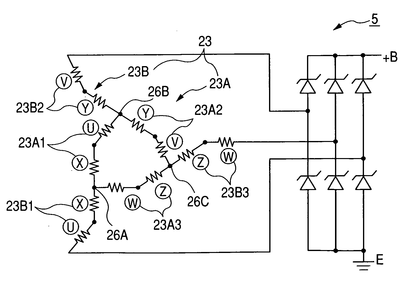
[0033]The stator 2 includes a stator core 22, an armature winding 23 wound around the stator core 22, and an insulator 24 for providing insulation between the stator core 22 and the armature winding 23. The stator core 22, which is made by laminating thin steel sheets, is formed with a plurality of slots (72 slots, in this embodiment) at its inner peripheral surface. The armature winding 23 is constituted by two sets of three-phase windings 23A and 23B located in the 72 slots formed in the stator core 22. The armature winding 23 is explained in more detail later.

[0034]The rotor 3, which rotates together with a shaft 6, includes Lundell-type pole cores 7, a field coil 8, sliprings 9 and 10, a diagonal fan 11, and a centrifugal fan 12. The shaft 6 is coupled to a pulle...


PUM


Abstract

The electric rotating machine includes a rotor around which a field coil is wound, and a stator including a stator core around which an armature winding is wound. The armature winding includes a first three-phase winding whose phase coils are delta-connected to form a delta winding, and a second three-phase winding whose phase coils are connected to corresponding nodes of the delta winding to form a star winding. The delta winding and the star winding are wound around the stator core such that the phase coils of the delta winding and the phase coils of the star winding share the same slots of the stator core.

Description

CROSS-REFERENCE TO RELATED APPLICATION[0001]This application is related to Japanese Patent Application No. 2007-238944 filed on Sep. 14, 2007, the contents of which are hereby incorporated by reference.BACKGROUND OF THE INVENTION[0002]1. Field of the Invention[0003]The present invention relates to an electric rotating machine such as an alternator (generator) mounted on a passenger car or a truck.[0004]2. Description of Related Art[0005]In recent years, there has been an increasing demand for a vehicle alternators driven by an engine mounted on a vehicle, which generate less magnetic noise at the time of power generation, in order to contribute to upgrading the vehicle. However, on the other hand there has been an increasing demand for vehicle alternators having high power generation capacity because of an increase of electrical load due to an increased number of safety control devices and the like mounted on the vehicle. Accordingly, it has been required to provide small-sized, low...

Claims


Application Information

Patent Timeline
Patent Type & Authority Applications(United States)
IPC IPC(8): H02K23/34
CPCH02K19/34H02K3/28
Inventor KOIKE, AKIHITO
Owner DENSO CORP
Why Eureka
Try Eureka