
Fastening mechanism

a technology of fastening mechanism and fastening plate, which is applied in the direction of electrical apparatus construction details, instruments, and electrical apparatus casings/cabinets/drawers, etc., can solve the problems of occupying more space, preventing short circuits, and facilitating effective heat dissipation , the effect of simple structur

Inactive Publication Date: 2009-03-19
INVENTEC CORP
View PDF18 Cites 20 Cited by
  • Summary
  • Abstract
  • Description
  • Claims
  • Application Information

AI Technical Summary

Benefits of technology

[0009]The present invention aims to eliminate the aforementioned drawbacks, and, as such, an objective of the present invention is to provide an effective fastening mechanism for an electronic equipment that does not take as much space as required in the prior art and thus can save the inner layout space of the electronic equipment.
[0010]Another objective of the present invention is to provide a fastening mechanism for an electronic equipment that facilitates installation and thus increases efficiency.
[0013]In addition, the fastening mechanism may further include an insulation body disposed between the second module and the lid body and thereby short circuits can be prevented. The lid body includes an accommodating portion for accommodating the first module, and may further include a plurality of cooling openings for facilitating effective heat dissipation.
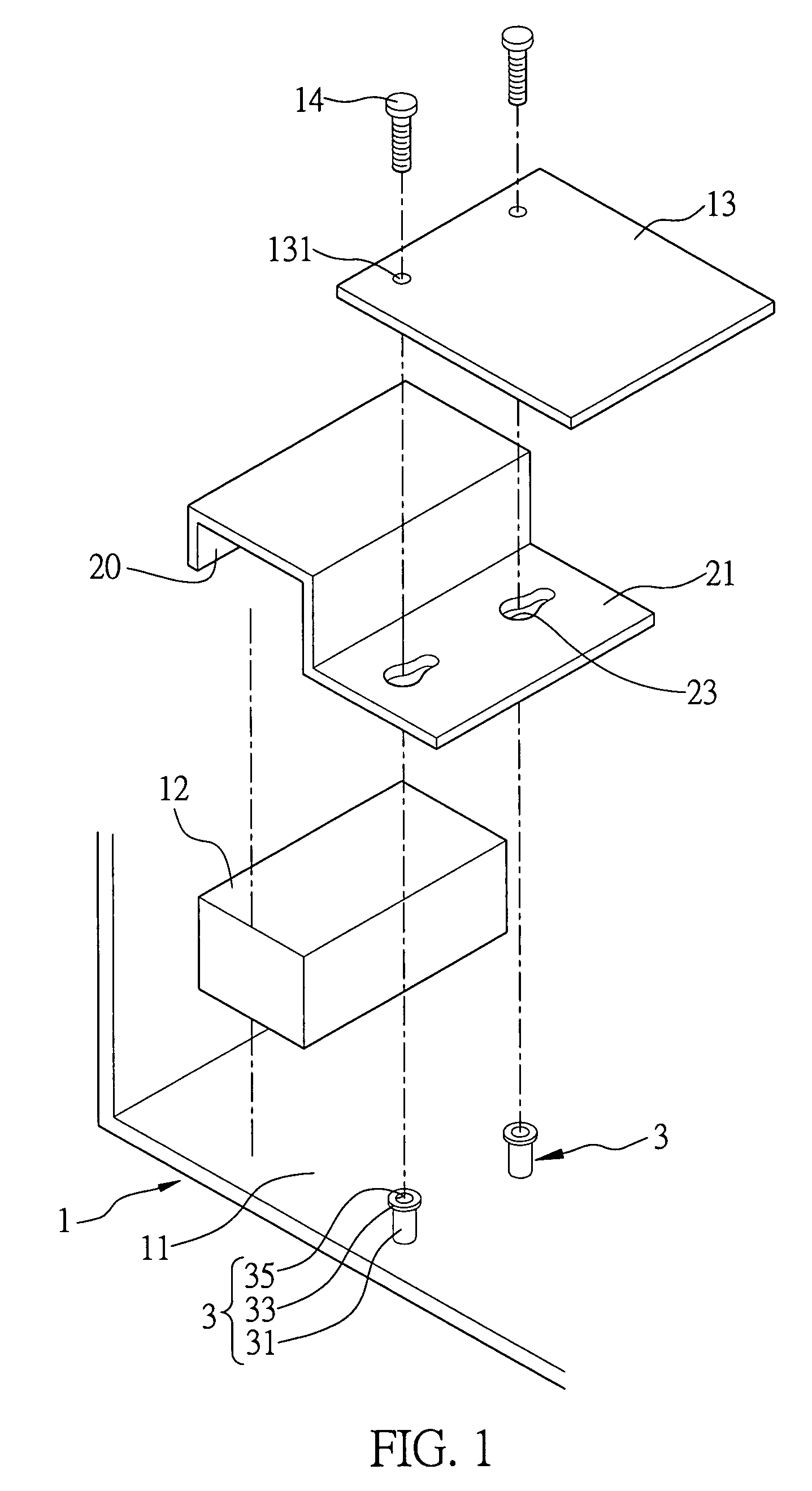
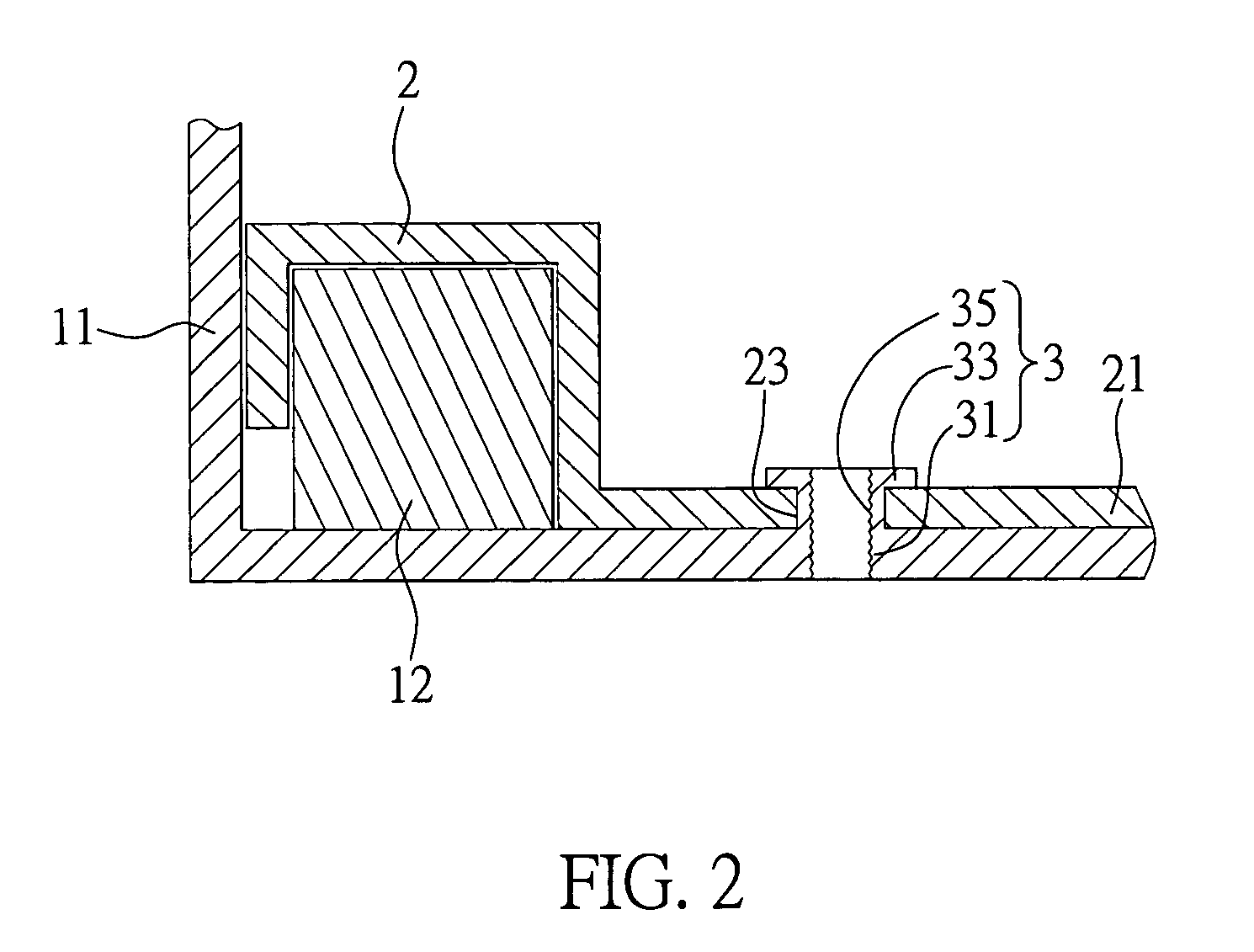
[0014]Compared to the prior art techniques, the present invention provides a lid body attached to the housing of the electronic equipment, wherein the lid body includes an accommodating portion for receiving a first module and includes an extending portion overlapping a second module and fastened to the housing by means of a positioning member, such that the lid body, the first and second modules can be concurrently secured in position within the housing to save the layout space, thereby providing a simple structure for easy installation and improving assembly efficiency.
[0015]In addition, the fastening mechanism of the present invention has a simple structure, is easy to be manufactured and has low cost.

Problems solved by technology

Conventional power supplies for servers cannot meet the requirements of energy consumption, especially for middle-scale and high-end servers.
However, the redundant power supply consists of multiple single power supplies and thus occupies more space than one single power supply in a server unit.
Moreover, a motherboard is usually installed in the server near the area surrounding the power supply unit, which necessitates the use of respective fastening mechanisms for fastening both the power supply unit and the motherboard in respective positions, thus requiring more space for accommodating respective fastening mechanisms in the server.
Hence, it leads to an inconvenient and inefficient installation due to the limited space in a server.
However, the approach to modify the housing is strictly limited by standard specifications such as SSI and ATX and thus it is difficult to realize such approach.
And even if it can be realized, the perspective on its marketablity is also doubtful.
Similarly, the alteration of existing motherboards is not promising either and the perspective in designing new redundant-typed power supplies for such purposes will only incur more costs and does not provide industrial applicability to solve the problem.

Method used


Image

  • Fastening mechanism
  • Fastening mechanism
  • Fastening mechanism

Examples


Embodiment Construction

[0022]The following illustrative embodiments are provided to illustrate the disclosure of the present invention, these and other advantages and effects can be apparently understood by persons skilled in the art after reading the disclosure of this specification. The present invention can also be performed or applied by other different embodiments. The details of the specification may be on the basis of different points and applications, and numerous modifications and variations can be devised without departing from the spirit of the present invention.

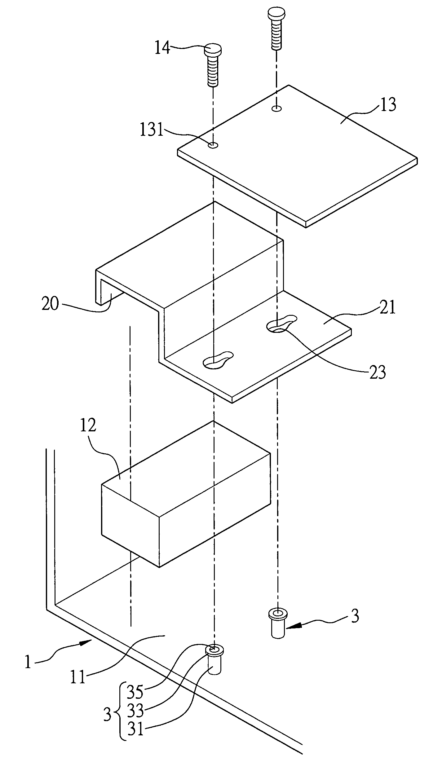
[0023]Please refer to FIG. 1, which is a schematic view showing the fastening mechanism according to the first preferred embodiment of the present invention. As illustrated, the fastening mechanism is applicable for fastening a first module 12 and a second module 13 to the housing 11 of an electronic device 1, wherein the second module 13 includes a plurality of first engaging portions 131 to be accommodated in the housing 11 of the ele...


PUM


Abstract

A fastening mechanism for fastening a module and a second module in the housing of an electronic device is disclosed. The fastening mechanism includes a lid body and a positioning member disposed in the housing. The first module is fixed in the housing by the lid body and the lid body is fastened by the positioning member, which is coupled to and overlaps the second module on the lid body, thereby using a shared common space for concurrently holding the lid body, the first module and the second module in place to save the layout space of the electronic device.

Description

BACKGROUND OF THE INVENTION [0001]1. Field of the Invention[0002]The present invention relates to fastening mechanisms, and more particularly, to a fastening mechanism for an electronic equipment.[0003]2. Description of the Related Art[0004]In the rapid development of internet, servers used for internet are well-developed, and requirements for a power supply of a server are growing.[0005]Conventional power supplies for servers cannot meet the requirements of energy consumption, especially for middle-scale and high-end servers. Currently, the ATX power supply is commonly a standard power supply for PC and servers. The ATX power supply includes single and redundant power supplies. The single power supply, which has low power consumption, is mainly used for PCs and low-end servers, whereas the redundant power supply is commonly used in middle-scale and high-end server equipment to ensure its reliability in supplying power without failure, as mentioned above.[0006]However, the redundant...

Claims


Application Information

Patent Timeline
IPC IPC(8): G06F1/16H05K7/00
CPCG06F1/184H05K7/1487G06F1/188
Inventor HU, TIGERCHENG, TSAI-KUEI
Owner INVENTEC CORP
Learn More