Magnetoresistive sensor memory with multiferroic material

a multi-ferroic material and magnetic anisotropy technology, applied in the field of data memory, can solve the problems of limited size of existing solid-state non-volatile memory devices such as mram, flash memory, spin ram, and limited practical performance in terms of long-term non-volatile or in terms of memory size, and achieve the effect of lower magnetic anisotropy and higher magnetic anisotropy

Inactive Publication Date: 2009-03-19
SEAGATE TECH LLC
View PDF17 Cites 13 Cited by
  • Summary
  • Abstract
  • Description
  • Claims
  • Application Information

AI Technical Summary

Benefits of technology

[0006]According to one aspect, the multiferroic material receives a modulation potential that modulates magnetic anisotropy of the multiferroic material. According to another aspect, the modulation provides a relatively lower

Problems solved by technology

Existing solid state non-volatile memory devices such as MRAM, flash memory, spin RAM have limited size (in comparison with disc drives) and have practical performance limits in terms of long term non-volatility or in terms of memory size.
One technical difficulty with MRA

Method used


Image

  • Magnetoresistive sensor memory with multiferroic material
  • Magnetoresistive sensor memory with multiferroic material
  • Magnetoresistive sensor memory with multiferroic material

Examples


Embodiment Construction

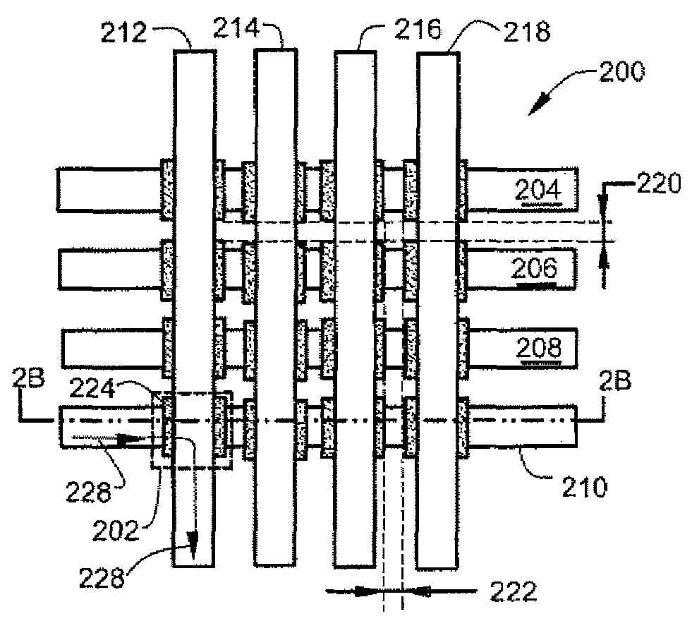
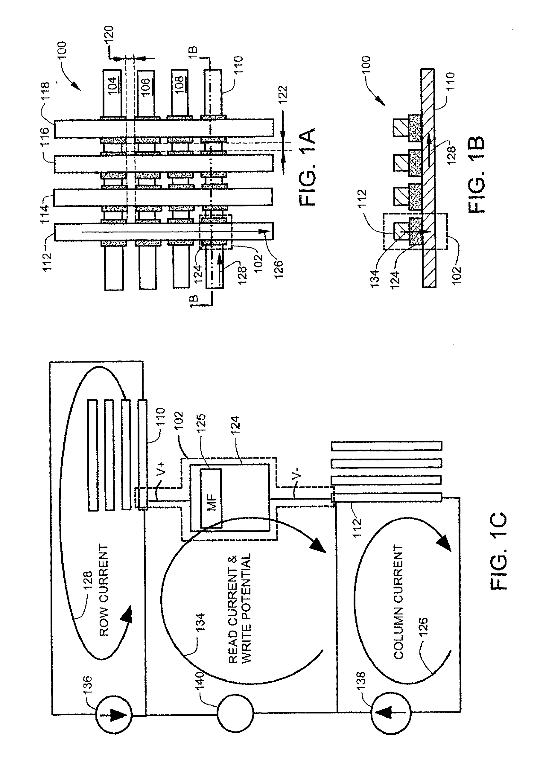
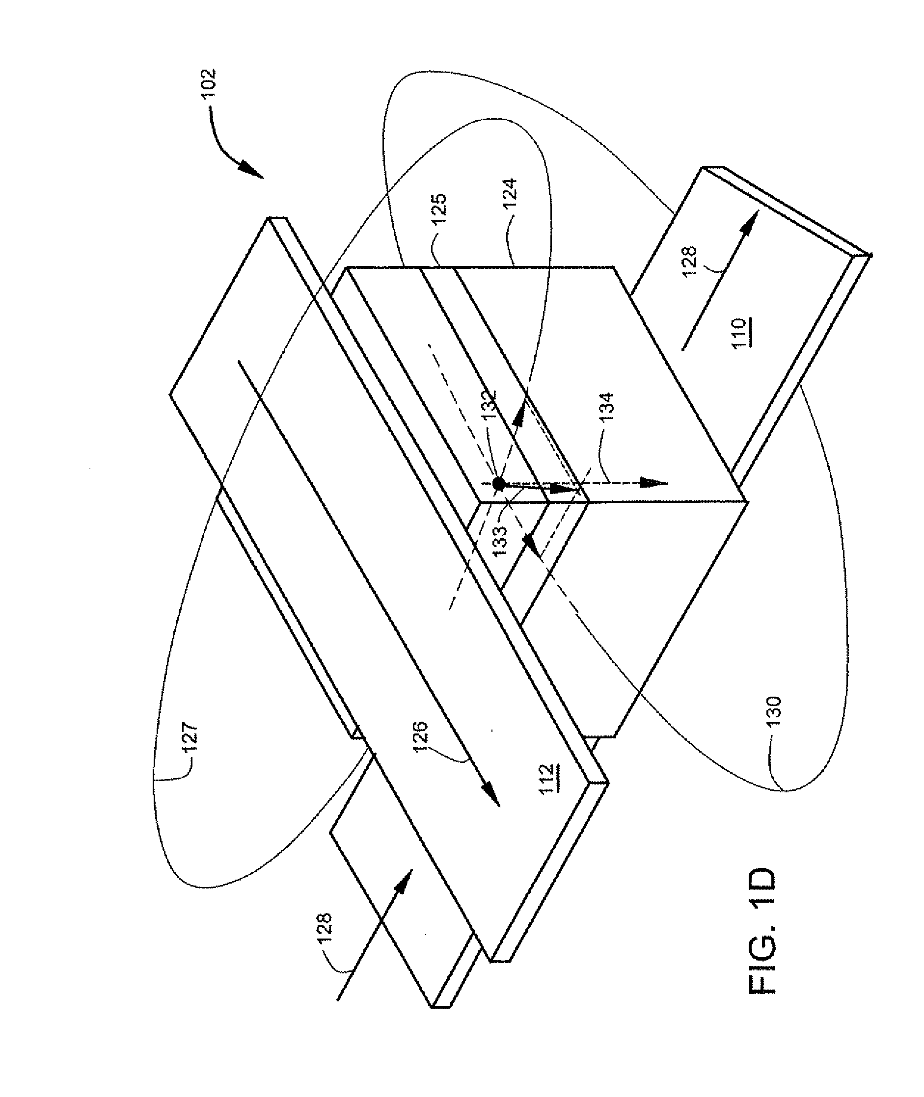
[0014]According to one aspect an array of memory cells comprises row write conductors and column conductors that cross. The row conductors cross the column conductors at cross points. Memory cells are located between the row and column conductors at the cross points. Individual memory cells are addressable at the cross points. Each memory cell comprises a magnetoresistive sensor that includes a layer of multiferroic material. The multiferroic material receives a modulation potential that modulates the magnetic anisotropy of the multiferroic material. The modulation provides a lower magnetic anisotropy during a write interval. In another aspect, magnetic anisotropy can also be increased during a read interval. In yet another aspect, a free layer in the magnetoresistive sensor comprises the multiferroic material.

[0015]As used in this application, the term “multiferroic material” refers to a material that has both piezoelectric and ferromagnetic properties. Of particular interest are m...


PUM


Abstract

A memory cell includes a magnetoresistive sensor that comprises layers that include a free layer. The magnetoresistive sensor conducts a read current representative of data stored in the memory cell during a read interval. A first write conductor carries a write current that writes data in the free layer. At least one of the layers comprises a multiferroic layer formed of multiferroic material.

Description

FIELD OF THE INVENTION[0001]The present invention relates generally to data memory, and more particularly but not by limitation to non-volatile data memory.BACKGROUND OF THE INVENTION[0002]Existing solid state non-volatile memory devices such as MRAM, flash memory, spin RAM have limited size (in comparison with disc drives) and have practical performance limits in terms of long term non-volatility or in terms of memory size. One technical difficulty with MRAM in particular is the difficulty of writing to one selected memory cell at a cross point without unduly exposing other memory cells in the same row or column as the selected memory cell to enough stray magnetic field to cause a stray write, in other words, a write error.[0003]Improvements are needed in the ability to write to a selected memory cell while maintaining high noise margins for other memory cells on the same row or same column as the selected memory cell.[0004]Various aspects of the present invention provide solutions...

Claims


Application Information

Patent Timeline
IPC IPC(8): G11C11/00
CPCB82Y25/00G01R33/093H01L43/08G11C11/16H01L27/222G01R33/096G11C11/161G11C11/1675H10B61/00H10N50/10
Inventor SEIGLER, MICHAEL ALLEN
Owner SEAGATE TECH LLC
Why Eureka
Try Eureka