Optical pickup and disc drive apparatus

a technology of optical pickups and disc drives, which is applied in the direction of optical recording heads, instruments, data recording, etc., can solve the problems of deterioration of optical pickup optical performance, affecting the servo characteristics of focusing and tracking, and the damper, which is configured using viscoelastic adhesive, etc., to achieve the effect of satisfying the servo characteristics during focusing and tracking

Inactive Publication Date: 2009-03-19
SONY CORP
View PDF5 Cites 2 Cited by
  • Summary
  • Abstract
  • Description
  • Claims
  • Application Information

AI Technical Summary

Benefits of technology

[0021]Thus, the disc drive apparatus including the optical pickup is free from functional deterioration such as that observed in a disc drive apparatus including the related-art optical pickup, which uses a viscoelastic adhesive, during use at high temperature, after a long period of use, and because of release of a volatile substance. Therefore, satisfactory servo characteristics during focusing and tracking can be ensured.

Problems solved by technology

The optical pickup disclosed in Japanese Unexamined Patent Application Publication No. 2004-171679 has a problem in that performance of the damper, which is configured using a viscoelastic adhesive, tends to be deteriorated during use at high temperature and after a long period of use because the viscoelastic adhesive is not sufficiently resistant to heat and its physical properties often change over time.
If the released volatile substance adheres to the objective lens, the optical performance of the optical pickup may be deteriorated.

Method used


Image

  • Optical pickup and disc drive apparatus
  • Optical pickup and disc drive apparatus
  • Optical pickup and disc drive apparatus

Examples


Embodiment Construction

[0027]Embodiments of an optical pickup and a disc drive apparatus according to the present invention will now be described with reference to the attached drawings.

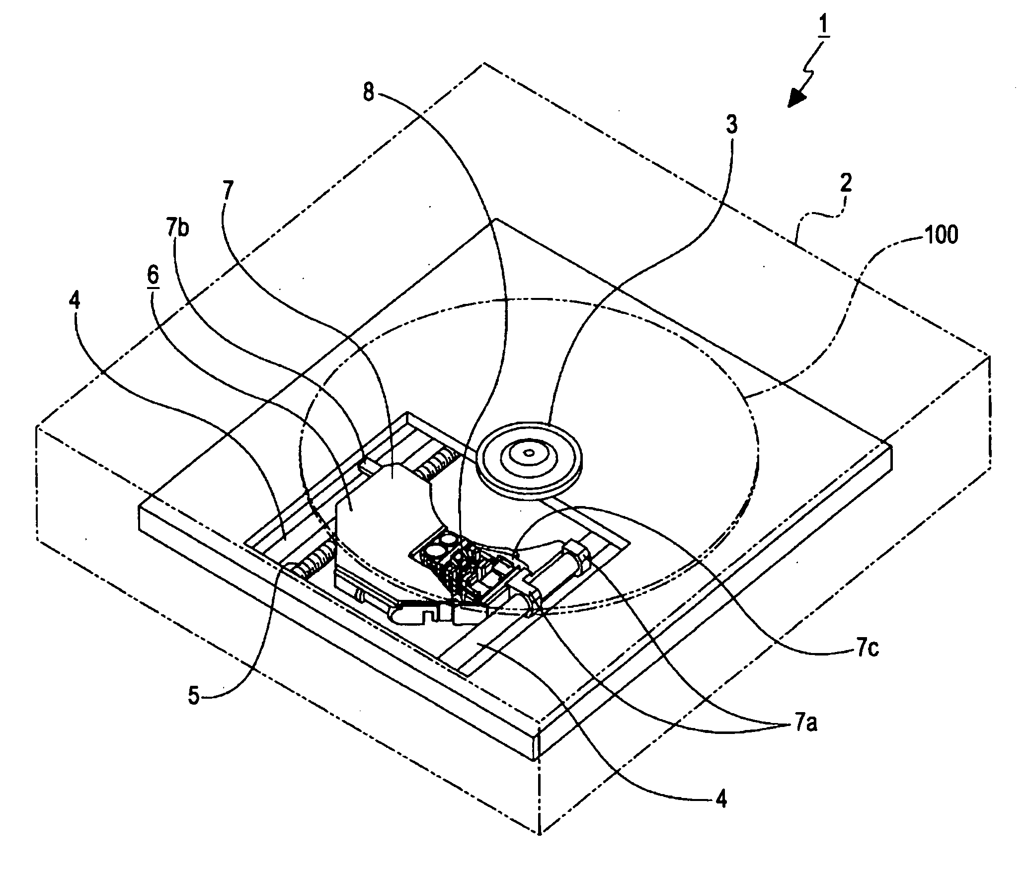
[0028]Referring to FIG. 1, a disc drive apparatus 1 has an outer casing 2, which houses relevant components and mechanisms. The outer casing 2 has a disc slot (not shown).

[0029]The outer casing 2 also houses a chassis (not shown). The chassis carries a spindle motor. A disc table 3 is secured to a motor shaft of the spindle motor.

[0030]The chassis also carries guide shafts 4 and 4, which are parallel to each other, and supports a lead screw 5 that is rotated by a feed motor (not shown).

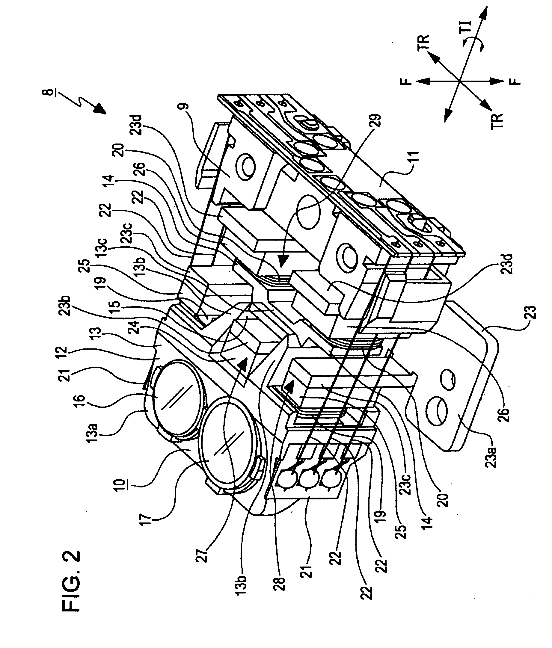
[0031]An optical pickup 6 includes a movable base 7, relevant optical components provided to the movable base 7, and an objective lens driving mechanism 8 mounted on the movable base 7. The movable base 7 is provided at ends thereof with bearings 7a and 7b, with which the movable base 7 is slidably supported by the guide shafts 4 and 4.

[0032...


PUM

PropertyMeasurementUnit
wavelengthaaaaaaaaaa

Abstract

An optical pickup includes a movable base and an objective lens driving mechanism mounted on the movable base. The objective lens driving mechanism includes a fixed block affixed to the movable base; a movable block having an objective lens and a lens holder holding the objective lens, the movable block moving in focusing, tracking, and tilting directions; supporting springs connecting the fixed block and the movable block; a focusing magnetic circuit including a focusing coil and a focusing magnet; a tracking magnetic circuit including a tracking coil and a tracking magnet; and a tilting magnetic circuit including a tilting coil and a tilting magnet. The lens holder includes a body holding the objective lens, and a thin segment projecting from the body and serving as a dynamic damper that absorbs vibration occurring in the movable block. The tilting coil or the tilting magnet is attached to the thin segment.

Description

CROSS REFERENCES TO RELATED APPLICATIONS[0001]The present invention contains subject matter related to Japanese Patent Application JP 2007-239359 filed in the Japanese Patent Office on Sep. 14, 2007, the entire contents of which are incorporated herein by reference.BACKGROUND OF THE INVENTION[0002]1. Field of the Invention[0003]The present invention relates to optical pickups and disc drive apparatuses. In particular, the present invention relates to a technical field in which satisfactory servo characteristics are ensured during focusing and tracking while functional deterioration is prevented by providing a thin segment serving as a dynamic damper with a movable block.[0004]2. Description of the Related Art[0005]Disc drive apparatuses perform recording and reproduction of information signals onto and from disc recording media such as optical discs and magneto-optical discs. Such a disc drive apparatus includes an optical pickup that is moved in the radial direction of a disc recor...

Claims


Application Information

Patent Timeline
Patent Type & Authority Applications(United States)
IPC IPC(8): G11B7/00
CPCG11B7/0935G11B2007/0006G11B7/1374G11B7/0956
Inventor ISOBE, HIROSHI
Owner SONY CORP
Why Eureka
Try Eureka