Microstructured device for removable storage of small amounts of liquid and a process for removal of the liquid stored in this device

a microstructured device and liquid storage technology, which is applied in the direction of liquid dispensing, withdrawing sample devices, material testing goods, etc., can solve the problems of large container shape dictating the design of the device, unable to be made individually, and higher liquid packing density

Active Publication Date: 2009-03-19
KADEL KLAUS +1
View PDF17 Cites 21 Cited by
  • Summary
  • Abstract
  • Description
  • Claims
  • Application Information

AI Technical Summary

Benefits of technology

[0008]In one advantageously configured microstructured device, the carrier is in one piece. The first cavity is molded in a carrier that consists of one piece. In contrast to a carrier that is made of several parts, or to a microstructured device, in which the first cavity is not part of the carrier, or is not molded into the carrier, because the carrier is made in one piece, a compact and simple construction is achieved. This construction has advantages especially in the production of the microstructured device.
[0028]In the second section of the cavity, or in the second cavity, and / or in the channel, which is downstream of the removal opening, there can be a means that enhances the capillary force. This means that enhances the capillary force is used to accelerate or enable the transport of liquid into the channel or through the removal opening. The means that enhances the capillary force can be microstructure elements, such as for example trenches, stelae, columns or the like, or a nonwoven fabric insert. It is possible for the microstructure elements combined with a nonwoven fabric insert to form the means that enhances the capillary force.

Problems solved by technology

The disadvantage in the use of containers for microstructured devices for removable storage of liquid is that the shape of the container largely dictates the design of the device.
The recesses, therefore, cannot be made individually for each carrier; this could lead, for example, to higher packing density of the liquids which are to be stored.
Another disadvantage is that a relatively great effort is expended to move the liquids into the containers in order to then insert the containers as such into the carrier.

Method used


Image

  • Microstructured device for removable storage of small amounts of liquid and a process for removal of the liquid stored in this device
  • Microstructured device for removable storage of small amounts of liquid and a process for removal of the liquid stored in this device
  • Microstructured device for removable storage of small amounts of liquid and a process for removal of the liquid stored in this device

Examples


Embodiment Construction

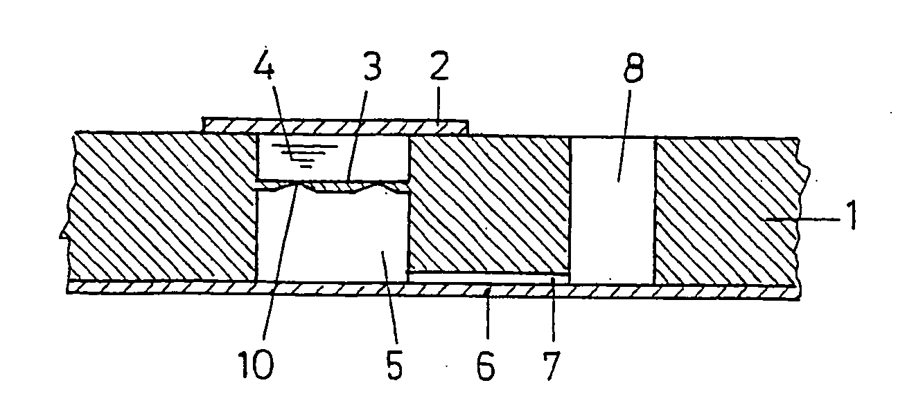
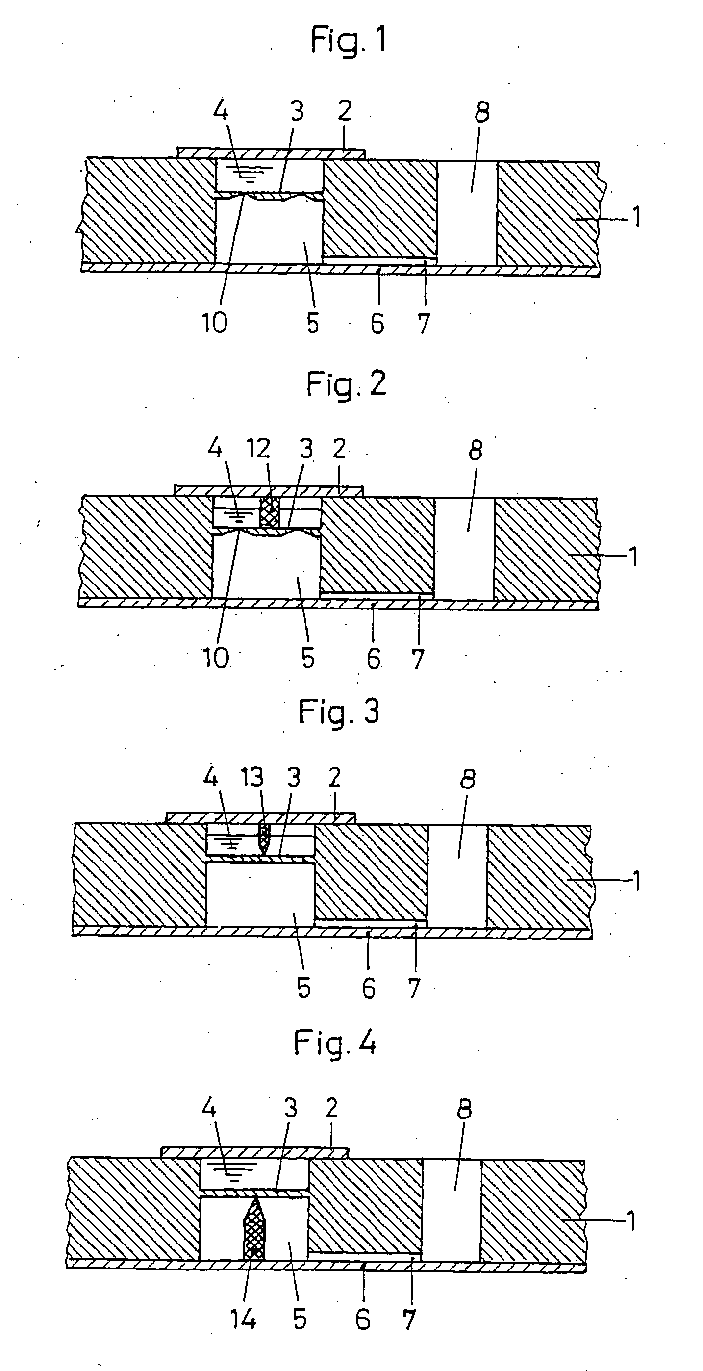
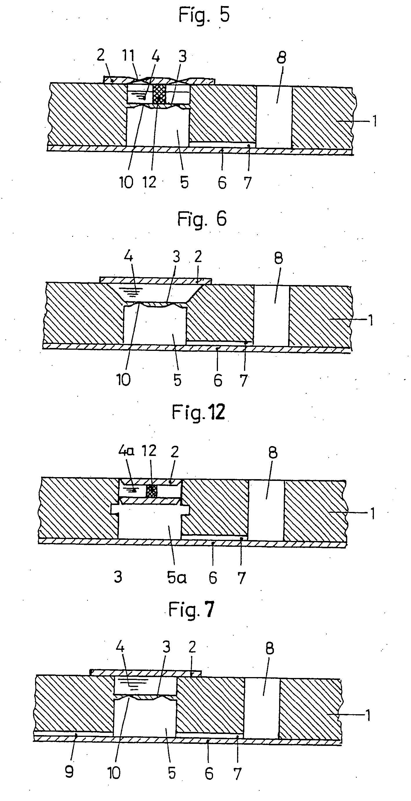
[0041]The embodiments shown in the FIGS. 1 to 16 for microstructured devices have great similarities, therefore the components that correspond to one another are provided with the same reference numbers.

[0042]The embodiment shown in the FIG. 1, in a section, has an advantageously plate-shaped carrier 1 into which recesses are made which are opposite one another from two sides and which are separated from one another by a blocking element 3. The opening of a recess is closed by a cover element 2, by which a first cavity 4 is formed between the cover element 2, the blocking element 3 and the sidewalls of the recess. This first cavity 4 is completely filled with a small amount of liquid. Likewise it is possible for the first cavity 4 to be filled only partially with the amount of liquid and to contain a small gas bubble. The other recess is closed with a film 6 that is applied to the surface of the carrier 1, in which surface there is a recess. In this way a second cavity 5 is formed w...


PUM


Abstract

Microstructured device for removable storage of small amounts of liquid with the following features: the device has a carrier; the device has a first cavity with at least one first section for storage of a small amount of liquid; the first section of the first cavity is molded into the carrier; the first section is closed with a cover element and a blocking element; the device has a means for transmission of a force from the cover element to the blocking element which destroys the connection between the blocking element and the carrier or destroys the blocking element itself so that the amount of liquid can be removed from the first section of the cavity.

Description

CROSS REFERENCES TO RELATED APPLICATIONS[0001]This application is a divisional of U.S. patent application Ser. No. 10 / 948,792, filed Sep. 24, 2004.BACKGROUND OF THE INVENTION[0002]This invention relates to a microstructured device for removable storage of small amounts of liquid and a process for removal of the liquid, which is stored in this device.[0003]The prior art discloses microstructured devices, which have a plate-shaped carrier in which recesses on one side are formed. These recesses are connected, via channels, to removal chambers, via which a liquid can be removed from the device. The recess is connected via a feed channel to an inlet chamber via which a sample or a flushing liquid can be delivered to the device. The sample is then transported as a result of transport forces, for example as a result of capillary forces, or pressure forces, to the recess and travels from there via the removal channel to the removal opening. So-called containers are inserted into the initia...

Claims


Application Information

Patent Timeline
Patent Type & Authority Applications(United States)
IPC IPC(8): B01L3/00F15C5/00B65D83/00F16K99/00
CPCB01L3/5025Y10T436/2575B01L3/5085B01L3/523B01L2200/16B01L2300/044B01L2300/047B01L2300/0672B01L2400/0638B01L2400/065F16K99/0001F16K99/0017F16K99/003F16K99/0034B01L3/502738
Inventor KADEL, KLAUSBLANKENSTEIN, GERT
Owner KADEL KLAUS
Why Eureka
Try Eureka