Power generation control device

a power generation control and control device technology, applied in the direction of electric generator control, mechanical equipment, machines/engines, etc., can solve the problems of low engine output torque, difficult to reduce torque fluctuation, unstable engine operation, etc., and achieve the effect of smoothing torqu

Inactive Publication Date: 2009-03-26
HONDA MOTOR CO LTD
View PDF4 Cites 6 Cited by
  • Summary
  • Abstract
  • Description
  • Claims
  • Application Information

AI Technical Summary

Benefits of technology

[0010]It is accordingly an object of the present invention to provide a power generation control device which can smooth the torque particularly in a low engine speed region by controlling the amount of the power generation period in consideration of the friction in each stroke.

Problems solved by technology

Accordingly, in the case that the amount of power generation period is controlled only based on the loaded condition of the engine without considering this friction, it is difficult to reduce torque fluctuation due to the friction difference between the strokes.
Particularly in the case that the engine is operated in a low engine speed region, the output torque of the engine is generally low.
Accordingly, even though the amount of power generation period is limited, there is a possibility that the engine operation may become unstable due to the torque fluctuation caused by the friction difference between the strokes.
In other words, even though the amount of power generation period is controlled according to only the loaded condition of the engine in general, the smoothness of the engine operation cannot be significantly improved.

Method used


Image

  • Power generation control device
  • Power generation control device
  • Power generation control device

Examples


Embodiment Construction

[0027]The present invention will now be described in detail with reference to the accompanying drawings, wherein the same reference numerals will be used to identify the same or similar elements throughout the several views. It should be noted that the drawings should be viewed in the direction of orientation of the reference numerals.

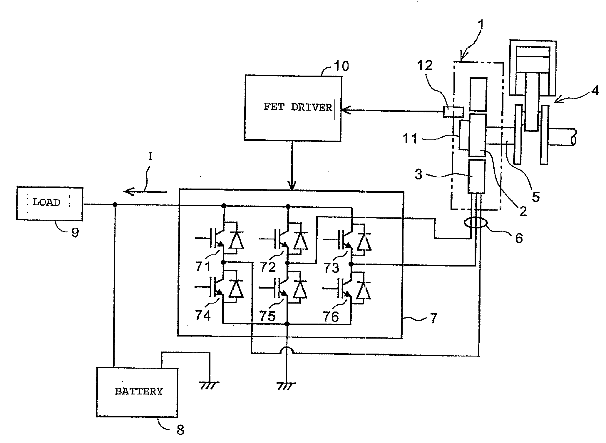
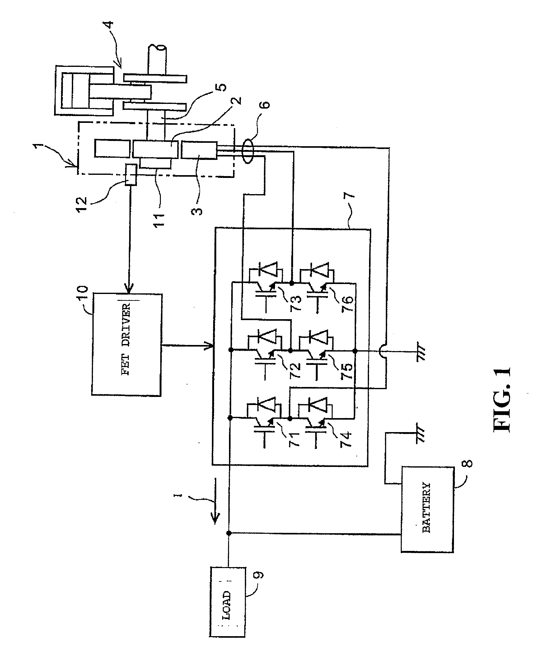
[0028]A preferred embodiment of the present invention will now be described with reference to the drawings. FIG. 1 is a diagram showing a system configuration of a charge control device according to a preferred embodiment of the power generation control device of the present invention.

[0029]In FIG. 1, a generator 1 is composed of an inner rotor 2 and an outer stator 3. The inner rotor 2 is connected to one end of a crankshaft 5 of a four-stroke cycle engine 4. The outer stator 3 has a three-phase output winding 6, which is connected to the input side of a switching circuit 7. The output side of the switching circuit 7 is connected to a battery 8 and a ...


PUM


Abstract

A power generation control device for a generator driven by a four-stroke cycle engine is provided. The power generation control device includes a switching circuit for controlling an output current from the generator; and a power generation period control device configured to operate the switching circuit to output the output current from the generator in only a predetermined power generation period of the four strokes of the engine, wherein the power generation period ranges from an expansion stroke to an intake stroke of the four strokes.

Description

CROSS-REFERENCE TO RELATED APPLICATIONS[0001]This nonprovisional application claims priority under 35 U.S.C. § 119(a) on Patent Application No. 2007-247867, filed in Japan on Sep. 25, 2007, the entirety of which is incorporated herein by reference.BACKGROUND OF THE INVENTION[0002]1. Field of the Invention[0003]The present invention relates to a power generation control device, and more particularly to a power generation control device for controlling power generation so that an output current generated from an engine driven generator can be supplied to a battery and a load in only a predetermined region of the engine strokes where a friction in the engine is low.[0004]2. Background of the Invention[0005]In a vehicle adapted to be driven by an engine, such as a motorcycle and a four-wheel vehicle, a generator adapted to be driven by the engine is provided. A battery for supplying electric power to be used in the vehicle is charged with an output current generated from the generator. ...

Claims


Application Information

Patent Timeline
Patent Type & Authority Applications(United States)
IPC IPC(8): H02P9/00
CPCH02P9/02H02P9/08
Inventor SAITO, KENJIROSHIBATA, KAZUMI
Owner HONDA MOTOR CO LTD
Why Eureka
Try Eureka