Ultrasonic device with a disk-shaped resonator

a technology of ultrasonic devices and resonators, applied in electrical equipment, mechanical vibration separation, chemical/physical/physical-chemical processes, etc., can solve the problems of microscopic bubbles (or cavities) that expand, implode violently, and expose materials to become intensely agitated

Inactive Publication Date: 2009-03-26
DR HIELSCHER
View PDF7 Cites 14 Cited by
  • Summary
  • Abstract
  • Description
  • Claims
  • Application Information

AI Technical Summary

Problems solved by technology

This results in the formation of microscopic bubbles (or cavities) that expand during low pressure cycles and implode violently during high pressure cycles.
Cavitation generates high shear forces at the sonotrode tip and causes the exposed material to become intensely agitated.

Method used


Image

  • Ultrasonic device with a disk-shaped resonator
  • Ultrasonic device with a disk-shaped resonator
  • Ultrasonic device with a disk-shaped resonator

Examples


example 1

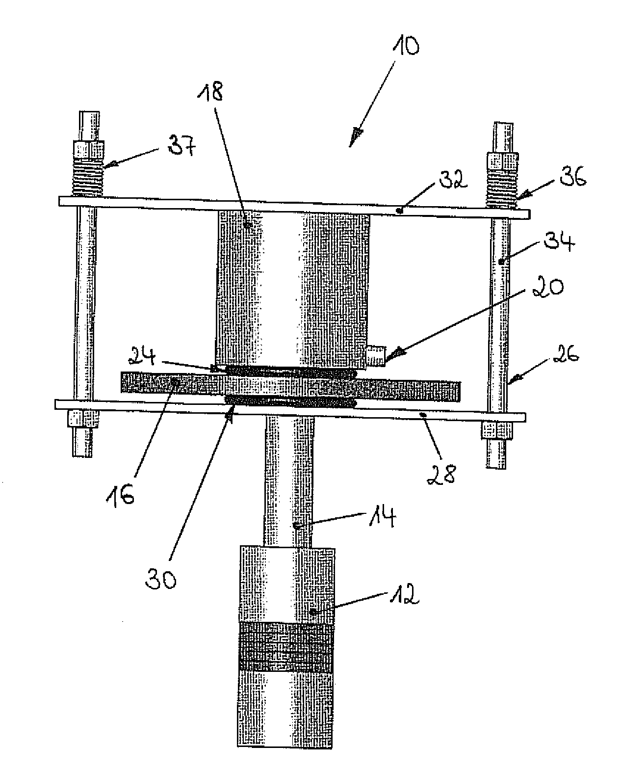
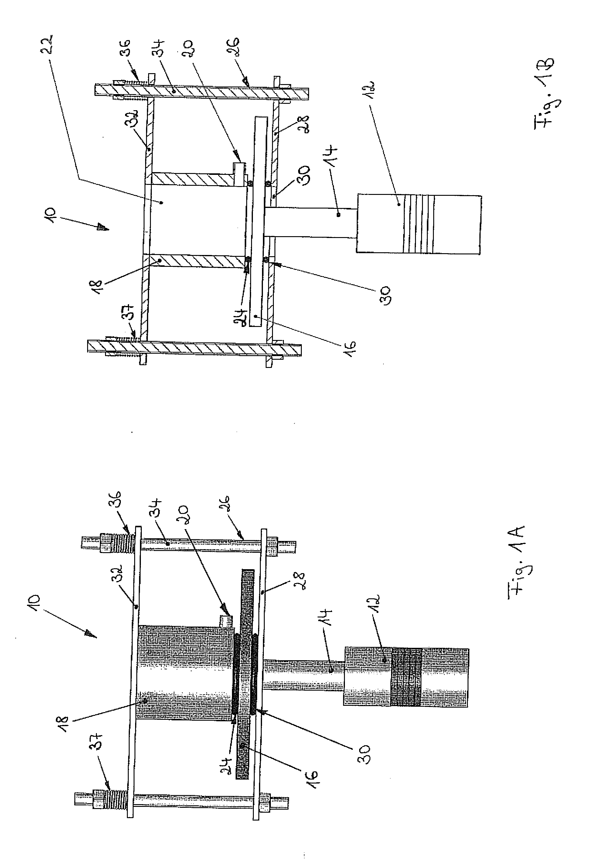
[0030]FIG. 1A and FIG. 1B (sectional view of FIG. 1A) show an ultrasonic device according to a first embodiment of the invention. An ultrasonic device 10 includes an ultrasound transducer 12 which is central connected by a booster horn 14 with a disk-shaped resonator 16. A cylindrical and bottom free container 18 is provided on an upper side of the resonator 16. The container 18 is construed as a continuous reactor having an outlet 20 near its bottom and an inlet 22 at its head. An O-ring 24 is provided between the container 18 and the resonator 16. The O-ring 24 acts as a sealing element, i.e. prevents that a liquid provided in an inner chamber of the container 18 leaks through the gap between container 18 and resonator 16 while exited by ultrasonic waves.

[0031]The resonator 16 rests upon a bottom plate 28 with a through hole 30 which is part of a support frame 26. An O-ring 30 is provided between the resonator 16 and the bottom plate 28 of the support frame 26. A plate 32 is movea...

example 2

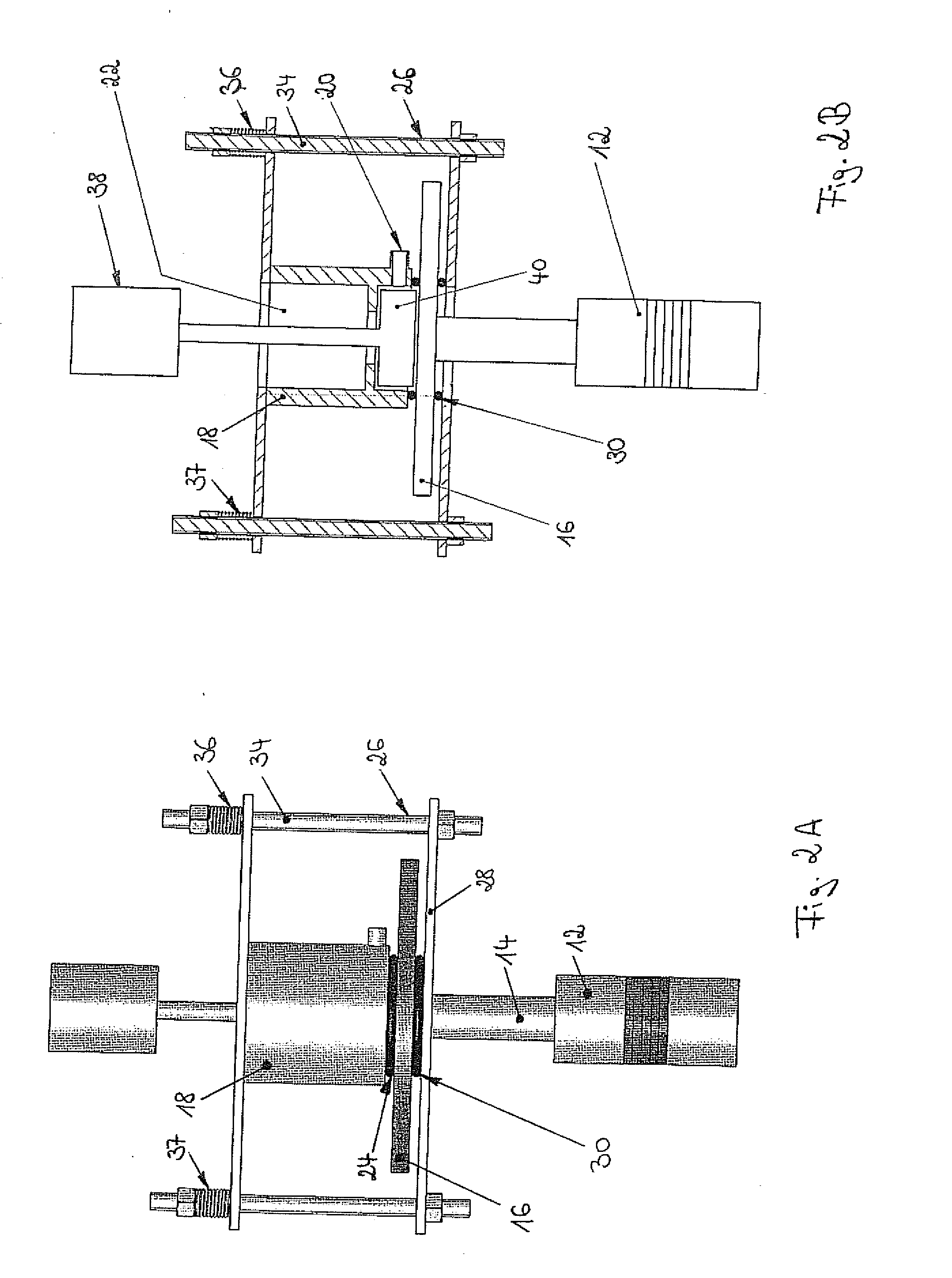
[0032]FIG. 2A and FIG. 2B (sectional view of FIG. 2A) illustrate an ultrasonic device according to a second embodiment of the invention. The second embodiment differs from the first embodiment of FIGS. 1A and 1B in that a motor driven stirrer 38 rests with its rotor 40 in a lower part the inner chamber of the container 18.


PUM


Abstract

The present invention refers to an ultrasonic device comprising an ultrasound transducer; and a disk-shaped metallic low-frequency ultrasound (NFLUS) resonator being mechanically connected with the ultrasound transducer on one side of the resonator; a container with an opening on its bottom side and being arranged on the other side of the disk-shaped resonator such that the opening is facing the disk-shaped resonator; an elastic sealing element arranged between the disk-shaped resonator and the container for sealing the container around the opening; and means for supplying a pressing force such that the container is tightened on the resonator during ultrasonication, but can be can be repeatedly disassembled and assembled after ultrasonication.

Description

FIELD OF THE INVENTION[0001]The invention refers to an ultrasonic device comprising a disk-shaped metallic low-frequency ultrasound (NFLUS) resonator and a bottom free container.TECHNICAL BACKGROUND OF THE INVENTION [0002]Ultrasonication is used in many applications, such as homogenizing, disintegration, sonochemistry, degassing or cleaning. Generally, an ultrasonic device includes an ultrasonic generator for generating electrical oscillations of ultrasonic frequency, i.e. above audible frequency. This energy is transmitted to a sonotrode. The sonotrode (also referred to as probe, horn or resonator) is a mechanical component that transmits the ultrasonic vibrations from an ultrasound transducer to the material to be sonified. It has to be mounted really tightly to avoid frictions and losses. Depending on the sonotrode geometry, the mechanical vibrations are amplified or reduced. At the sonotrode surface, the mechanical vibrations are coupled into the liquid. This results in the form...

Claims


Application Information

Patent Timeline
Patent Type & Authority Applications(United States)
IPC IPC(8): B06B1/06
CPCB01J19/008B01J19/10B06B3/00B01J2219/1943B01J2219/1946B01J2219/00961
Inventor HIELSCHER, HOLGERHIELSCHER, THOMASHIELSCHER, HARALD
Owner DR HIELSCHER
Why Eureka
Try Eureka