Counter Circuit, Control Signal Generating Circuit Including the Counter Circuit, and Display Apparatus

a counter circuit and control signal technology, applied in the counter field, can solve problems such as undesirable problems, and achieve the effects of reducing the circuit size, preventing an increase in the number of counter bits, and small circuit siz

Inactive Publication Date: 2009-03-26
SHARP KK
View PDF10 Cites 10 Cited by
  • Summary
  • Abstract
  • Description
  • Claims
  • Application Information

AI Technical Summary

Benefits of technology

[0023]According to the invention, the selector circuit selects, from among a plurality of pulse signals, a pulse signal which is to be supplied to the counter. As such, a single counter can be shared by the plurality of pulse signals. This prevents an increase in the number of bits of the counter. This allows a reduction in circuit size of a circuit when the circuit is configured so as to (i) include the counter and (ii) generate a signal with the use of an output signal of the counter.
[0024]As a result, it is possible to ensure the effect of realizing a counter circuit that allows a circuit for generating a signal based on an output of a counter to have a sufficiently small circuit size.

Problems solved by technology

This causes a problem that the timing signal generating circuit 38 necessitates a large circuit size.
This problem is undesirable because the layout of the display panel 32 in the liquid crystal display apparatus 31 is greatly constrained.

Method used


Image

  • Counter Circuit, Control Signal Generating Circuit Including the Counter Circuit, and Display Apparatus
  • Counter Circuit, Control Signal Generating Circuit Including the Counter Circuit, and Display Apparatus
  • Counter Circuit, Control Signal Generating Circuit Including the Counter Circuit, and Display Apparatus

Examples


Embodiment Construction

[0047]The following describes an embodiment of the present invention with reference to FIGS. 1 through 7.

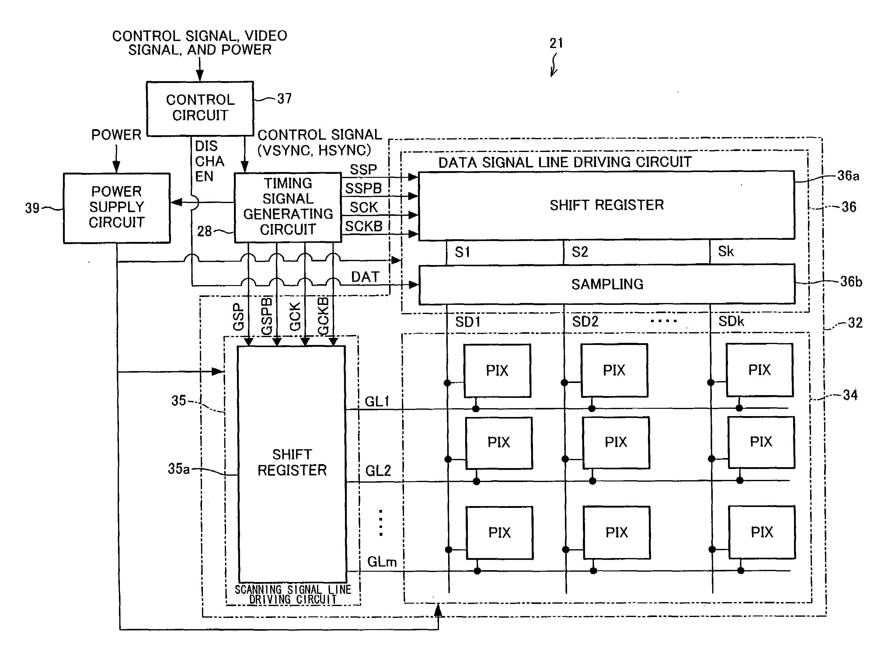
[0048]FIG. 7 illustrates an arrangement of a liquid crystal display apparatus 21 of the present embodiment. The liquid crystal display apparatus 21 is realized by replacing a timing signal generating circuit 38 in a liquid crystal display apparatus 31 illustrated in FIG. 8 with a timing signal generating circuit 28. A counter circuit of the present embodiment is included in the timing signal generating circuit 28. The counter circuit is realized by replacing, in the timing signal generating circuit 38 of the liquid crystal display apparatus 31 illustrated in FIG. 8, either conventional counter circuit illustrated in FIG. 10 or FIG. 12 with a counter circuit 1 illustrated in FIG. 1. In the present embodiment, a counter provided in the counter circuit 1 is a synchronous counter. However, an asynchronous counter may be alternatively adopted.

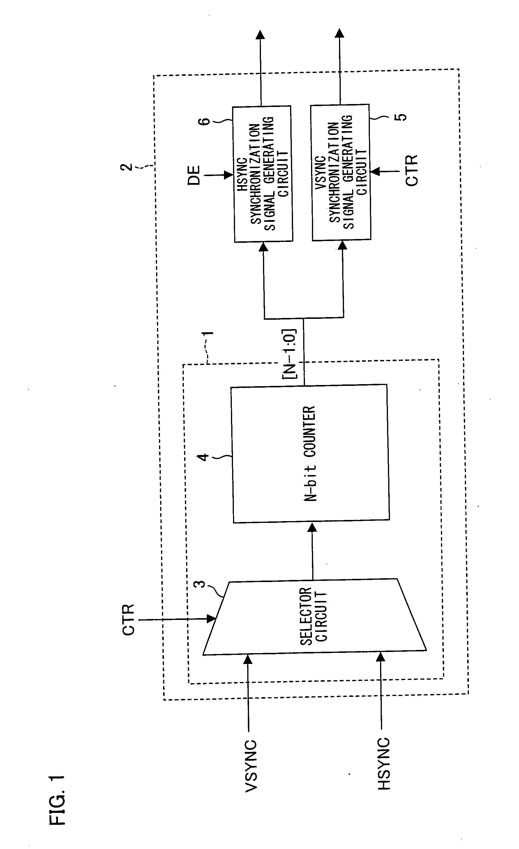
[0049]The counter circuit 1 illustrated in...


PUM


Abstract

In a counter circuit of a control signal generating circuit, a selector circuit selects under control which is in accordance with a selector circuit control signal (CTR) a predetermined one in a signal VSYNC and a signal HSYNC, which are pulse signals, so as to input a pulse signal thus selected to a counter. The counter outputs a counted result of pulses of the inputted pulse signal. By use of the counted result, a VSYNC synchronization signal generating circuit or an HSYNC synchronization signal generating circuit generates a control signal to control the driving of image display.

Description

TECHNICAL FIELD[0001]The present invention relates to a counter circuit for generating a control signal that drives an apparatus such as a display apparatus.BACKGROUND ART[0002]In an active-matrix liquid crystal display apparatus, various control signals, causing a liquid crystal panel to be driven, are generated. These control signals are signals for controlling circuits such as a scanning signal line driving circuit, a data signal line driving circuit, and a power supply circuit. The following describes a general arrangement of such a liquid crystal display apparatus.[0003]FIG. 8 is a block diagram illustrating a liquid crystal display apparatus 31. The liquid crystal display apparatus 31 is arranged so as to include a display panel 32, a control circuit 37, a timing signal generating circuit 38, and a power supply circuit 39. The display panel 32 includes a display section 34 having pixels PIX aligned in a matrix manner, a scanning signal line driving circuit 35, and a data signa...

Claims


Application Information

Patent Timeline
Patent Type & Authority Applications(United States)
IPC IPC(8): G09G5/00G06M3/00H03K21/02
CPCG09G3/20G09G2310/08G09G5/18G09G3/3611
Inventor NAKAGAWA, YOUSUKE
Owner SHARP KK
Why Eureka
Try Eureka