

Magnetic recording head and magnetic recording device
a recording head and magnetic technology, applied in special recording techniques, recording information storage, instruments, etc., can solve the problems of slowing down temporarily the recording density, difficult to achieve such a high recording density, and difficulty in recording methods
- Summary
- Abstract
- Description
- Claims
- Application Information
AI Technical Summary
Benefits of technology
Problems solved by technology
Method used
Image

Examples
first embodiment
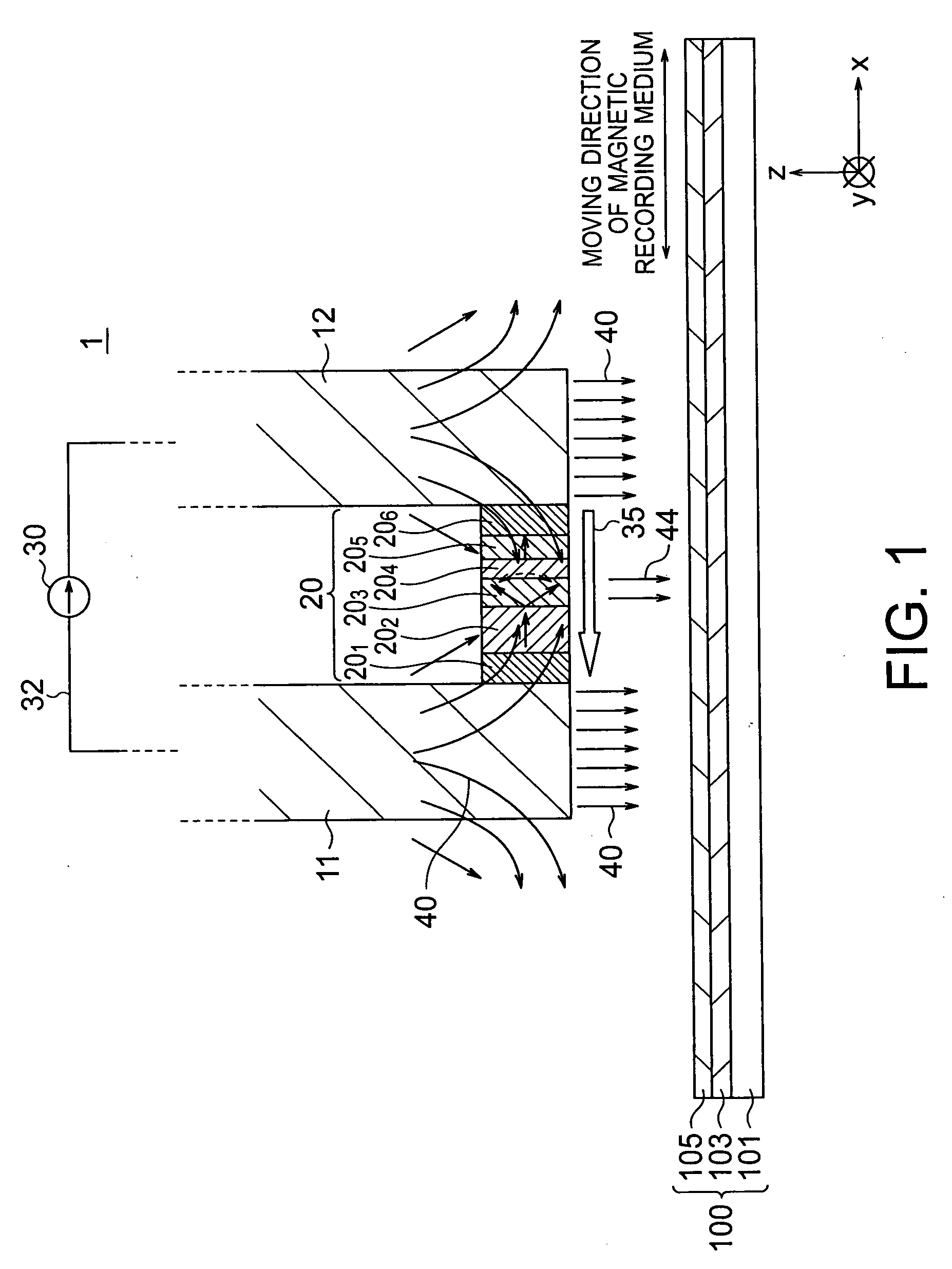
[0036]FIG. 1 shows a magnetic head in accordance with a first embodiment of the present invention. FIG. 1 is a cross-sectional view of the magnetic head 1, taken along a plane in a direction that is parallel to the moving direction of a magnetic recording medium 100 and is perpendicular to a plane facing the magnetic recording medium 100. As shown in FIG. 1, the moving direction of the magnetic recording medium 100 is toward the left-hand side or the right-hand side in the drawing.
[0037]The magnetic head 1 of this embodiment includes: main magnetic poles 11 and 12 that are arranged in the moving direction of the magnetic recording medium 100, and generate recording magnetic fields 40; a spin torque oscillator 20 that is provided between the main magnetic poles 11 and 12 and is located on the side of the magnetic recording medium 100; and a driving current source 30 that applies a driving current to the spin torque oscillator 20 via the main magnetic poles 11 and 12. The driving curr...
second embodiment
[0052]FIG. 6 shows a magnetic head in accordance with a second embodiment of the present invention. FIG. 6 is a cross-sectional view of the magnetic head 1B of this embodiment, taken along a plane in a direction that is parallel to the moving direction of the magnetic recording medium 100 and is perpendicular to a plane facing the magnetic recording medium 100. As shown in FIG. 6, the moving direction of the magnetic recording medium 100 is toward the left-hand side or the right-hand side in the drawing.
[0053]The magnetic head 1B of this embodiment is the same as the magnetic head 1 of the first embodiment shown in FIG. 1, except that the spin torque oscillator 20 is replaced with a spin torque oscillator 20A. The spin torque oscillator 20A includes an electrode 201, a bias layer 202, an oscillation layer 203, an intermediate layer 204, a spin injection layer 205, and an electrode 206. Unlike the spin torque oscillator 20 of the first embodiment, the spin torque oscillator 20A of th...
third embodiment
[0057]FIG. 7 shows a magnetic head in accordance with a third embodiment of the present invention. FIG. 7 is a cross-sectional view of the magnetic head 1C of this embodiment, taken along a plane in a direction that is parallel to the moving direction of the magnetic recording medium 100 and is perpendicular to a plane facing the magnetic recording medium 100. As shown in FIG. 7, the moving direction of the magnetic recording medium 100 is toward the left-hand side or the right-hand side in the drawing.
[0058]The magnetic head 1C of this embodiment is the same as the magnetic head 1B of the second embodiment shown in FIG. 6, except that the spin torque oscillator 20A is replaced with a spin torque oscillator 20B. The spin torque oscillator 20B includes an electrode 201, a bias layer 202, an oscillation layer 203, an intermediate layer 204, a spin injection layer 205, and an electrode 206. In the spin torque oscillator 20B of this embodiment, the magnetization directions of the bias l...
PUM
 Abstract
Description
Claims
Application Information