Image forming apparatus and image forming method

a technology of image forming apparatus and forming method, which is applied in the direction of inking apparatus, electrographic process, instruments, etc., can solve the problems of reducing the printing resolution, affecting the transfer properties, and affecting the output of the undried image when the recording medium is used, so as to achieve the effect of high quality

Inactive Publication Date: 2009-03-26
FUJIFILM CORP
View PDF3 Cites 54 Cited by
  • Summary
  • Abstract
  • Description
  • Claims
  • Application Information

AI Technical Summary

Benefits of technology

[0045]According to the present invention, since a recess-projection shape is formed in the intermediate transfer body before the ejection of ink droplets, and the recess-projection shape of the intermediate transfer body is crushed and flattened during transfer and recording, then the flow of ink on the intermediate transfer body during formation of the primary image is prevented, a sufficient contact surface area between the intermediate transfer bod

Problems solved by technology

However, there are problems in relation to print quality in that the print state varies with the paper quality, namely, with the type of the recording medium, for example, whether the medium is an OHP sheet, synthetic paper, normal paper, special inkjet paper, or the like.
In particular, when printing onto normal paper using a water-soluble ink which has generic versatility, there are problems in terms of reduction in the printing resolution due to bleeding or print-through during printing, in addition to which, depending on the drying properties of the ink on the recording medium after printing, a printed image which is an undried state when the recording medium is output may be disturbed.
In a transfer recording method, if the intermediate transfer body has little surface roughness, then a water repellency effect is liable to occur, whereas if the intermediate transfer body has a large surface roughne

Method used


Image

  • Image forming apparatus and image forming method
  • Image forming apparatus and image forming method
  • Image forming apparatus and image forming method

Examples


examples

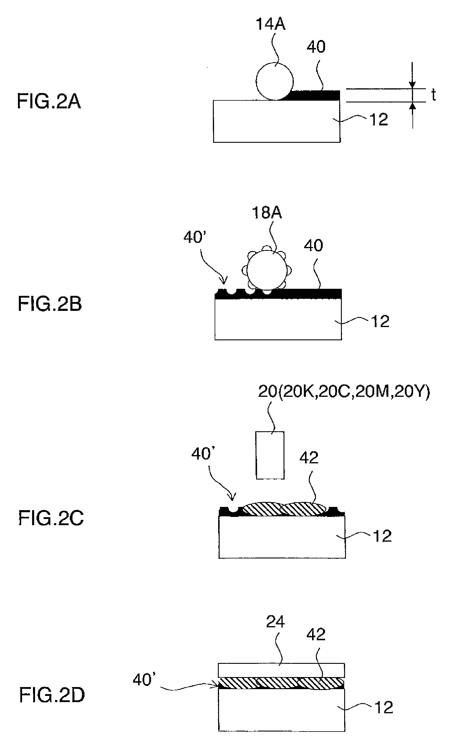
[0175]Next, concrete examples of the image forming method shown in the present embodiment will be described. In the concrete examples, ink droplets were ejected under the same conditions onto a resin layer formed with a recess-projection shape (Ra=1.2 μm, cycle 5 μm) and a resin layer not formed with a recess-projection shape (Ra=0.2 μm), and the marking properties and transfer properties were evaluated. The surface roughness of the resin layer was measured by a Violet Laser VK-9500 device manufactured by Keyence Corporation.

[0176]FIG. 9A shows the composition of the resin liquid (undercoating liquid) used in the concrete examples. In the concrete examples, the resin liquid illustrated in FIG. 9A was applied so as to form a thickness of 5 μm, and the solvent was driven off by heating for 10 seconds at 70° C. Subsequently, a metal recess-projection roller was pressed against the resin layer at a pressing force of 2.0 MPa, thereby forming a recess-projection shape in the resin layer.

[...

second embodiment

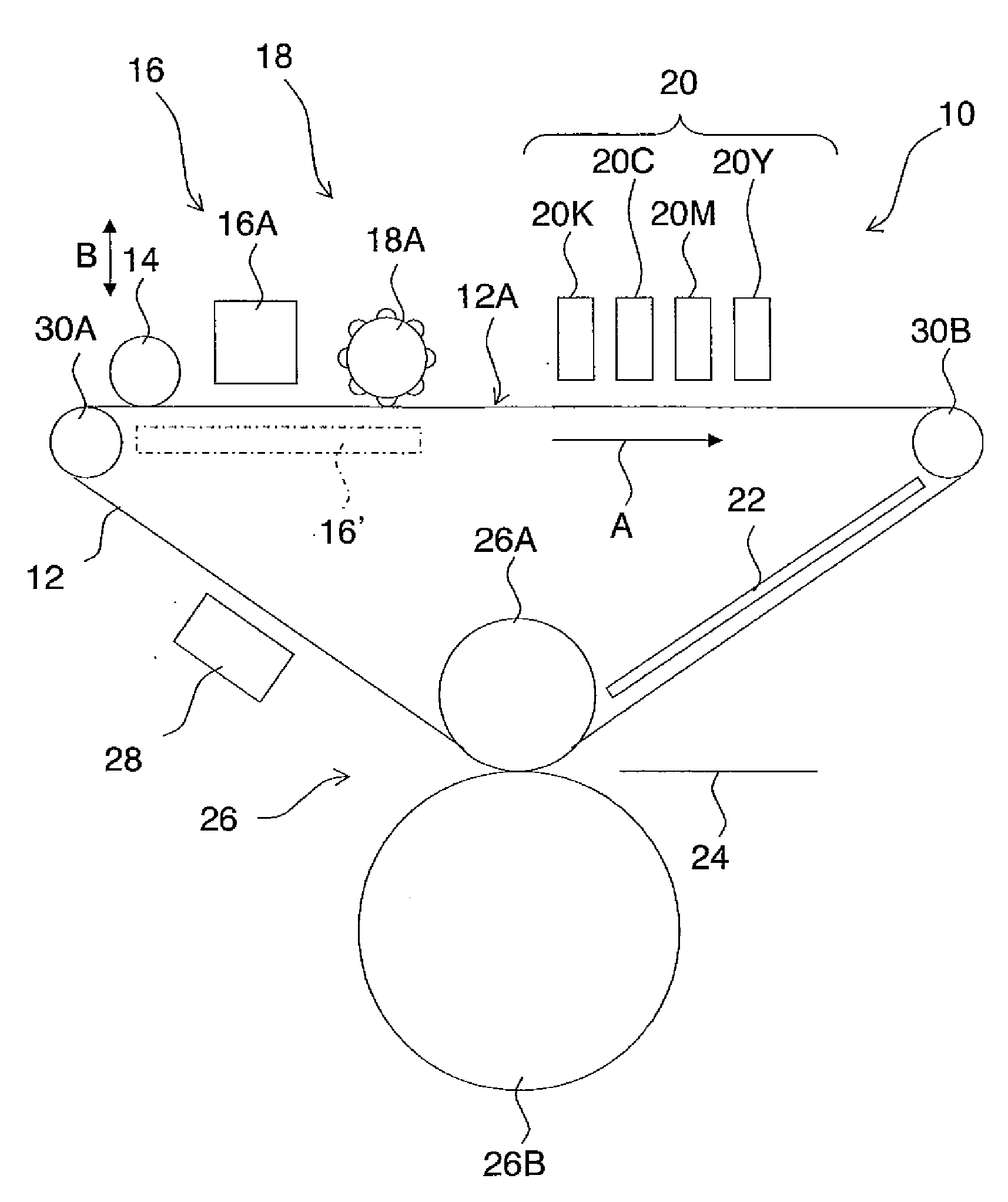
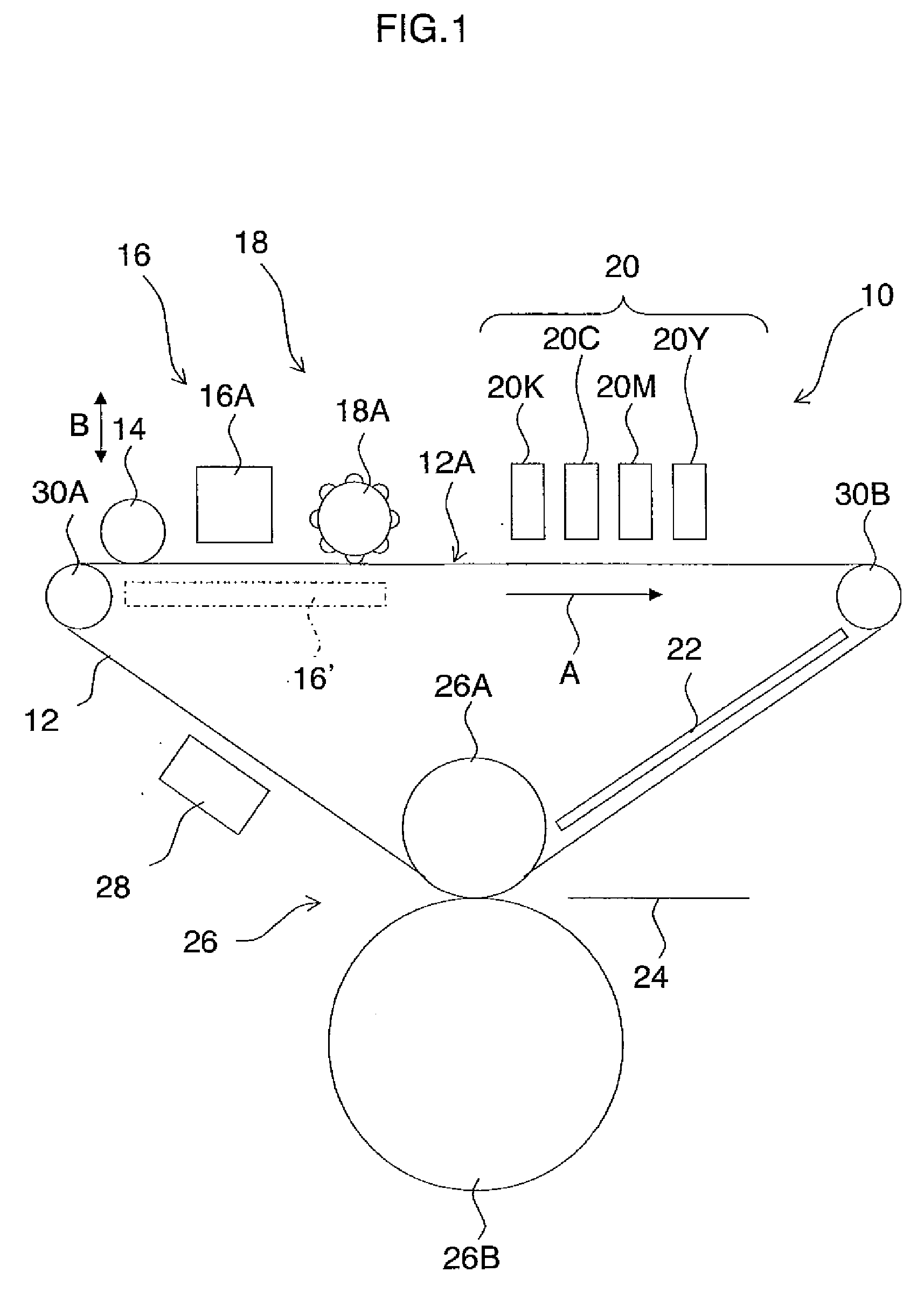
[0186]Next, a second embodiment of the present invention will be described. FIG. 11 shows the general composition of an inkjet recording apparatus 100 relating to the second embodiment of the present invention. In FIG. 11, parts which are the same as or similar to those illustrated in FIG. 1 are labeled with the same reference numerals and further explanation thereof is omitted here.

[0187]In the inkjet recording apparatus 100 illustrated in FIG. 11, a rubber layer (not illustrated in FIG. 11 and indicated by reference numerals 140 and 140′ in FIGS. 12A to 12D) is provided in the surface of an intermediate transfer body 112 (image forming surface 12A) and a recess-projection shape is formed directly in that rubber layer by means of the recess-projection forming unit 18. As a method of forming the recess-projection shape in the rubber layer, similarly to the inkjet recording apparatus 10 in FIG. 1, a method is employed in which a recess-projection roller 15A having recess-projection i...


PUM

PropertyMeasurementUnit
Viscosityaaaaaaaaaa

Abstract

An image forming apparatus which forms a primary image on an intermediate transfer body and then transfers the primary image onto a recording medium, has: a movement device which moves the intermediate transfer body in a movement direction; a recess-projection forming device which forms a recess-projection shape in an image forming surface of the intermediate transfer body; a droplet ejection device which is provided on a downstream side of the recess-projection forming device in terms of the movement direction and ejects droplets of ink onto the image forming surface of the intermediate transfer body in which the recess-projection shape has been formed, to form the primary image; and a transfer recording device which is provided on a downstream side of the droplet ejection device in terms of the movement direction and applies pressure to at least one of the intermediate transfer body and the recording medium in a state where the recording medium makes contact with the primary image formed on the image forming surface of the intermediate transfer body to transfer the primary image onto the recording medium.

Description

BACKGROUND OF THE INVENTION[0001]1. Field of the Invention[0002]The present invention relates to an image forming apparatus and image forming method, and for example, to image forming technology for forming dots by causing ink droplets to react with treatment liquid on an image forming body.[0003]2. Description of the Related Art[0004]At present, an inkjet recording apparatus is used favorably as a generic image forming apparatus which outputs images captured by a digital camera or duplicates images of a printed object, or the like. An inkjet recording apparatus can use paper and other various types of recording medium such as a resin sheet, a metal sheet and the like, and the most recent tendency is to be increasing demands for the output of high-quality images, regardless of the type of recording medium.[0005]However, there are problems in relation to print quality in that the print state varies with the paper quality, namely, with the type of the recording medium, for example, wh...

Claims


Application Information

Patent Timeline
IPC IPC(8): G03G15/16
CPCB41J2/01B41J2/14233B41J2/155B41J2/16585B41J2/175B41M5/03B41J2002/14459B41J2202/20B41J2202/21B41M5/0256B41J2002/012B41J2/16508B41J2/16526B41J2002/16529
Inventor YAMANOBE, JUNMAKUTA, TOSHIYUKICHIWATA, YUHEI
Owner FUJIFILM CORP
Why Eureka
Try Eureka