Charging system for vehicles

a charging system and vehicle technology, applied in the direction of driver input parameters, electric devices, driver interactions, etc., can solve the problems of complex manipulation of owners or occupants of vehicles, and incur an extra cos

Inactive Publication Date: 2009-03-26
DENSO CORP
View PDF11 Cites 100 Cited by
  • Summary
  • Abstract
  • Description
  • Claims
  • Application Information

AI Technical Summary

Benefits of technology

[0008]The present invention is intended to provide a charging system for vehicles that can prevent an incident such as theft of a charging cable, insertion of a foreign matter into a vehicle-side receptacle, or tampering with any other component, and that can be provided with such a security feature without the necessity of a time-consuming manipulation or a complex construction, even when an onboard battery, usable for running power, is charged from a household power supply at night or during vehicle down-time.
[0010]According to the charging system for vehicles, when an occupant leaves a vehicle, the switching action of the charging locking mechanism to the locked state is performed while being interlocked with the switching command of switching to the unlocked state of the door locking mechanism, for example, with a manipulation of locking the door locking mechanism using a key. Moreover, when the occupant boards the vehicle, the switching action of the charging locking mechanism to the unlocked state is performed while being interlocked with the switching command of switching to the unlocked state of the door locking mechanism, for example, with a manipulation of unlocking the door locking mechanism using the key. Thus, the interlocked locking control means controls interlock of the switching action of the charging locking mechanism between locking or the locked state and unlocking or the unlocked state in response to the switching command of switching the locking or locked state of the door locking mechanism and the unlocking or unlocked state thereof according to the positional relationship between the occupant and vehicle. Consequently, even when the onboard battery usable for running power is charged from a household power supply at night or during vehicle down-time, an incident such as theft of the charging cable, insertion of foreign matter into the vehicle-side receptacle, or tampering with any other component can be prevented. Moreover, the switching action of the charging locking mechanism between the locking and unlocking state is performed in response to the switching command of switching the locking of the door locking mechanism and the unlocking thereof normally issued from the occupant to the vehicle. Consequently, the above described security feature can be provided without the necessity of a time-consuming manipulation or a complex construction.
[0016]The foregoing portions of the interlocked locking control means control interlock of the switching action of at least one of the connector locking mechanism and cover locking mechanism between locking and unlocking in response to the switching command of switching locking of the door locking mechanism and unlocking thereof according to the positional relationship between the occupant and the vehicle. Consequently, theft of the charging cable, insertion of foreign matter into the vehicle-side receptacle, or tampering with any other component can be properly prevented. Moreover, the switching action of the connector locking mechanism or cover locking mechanism between the locking and unlocking is performed in the same direction as the direction from the occupant to the vehicle in which the switching command of switching the locking of the door locking mechanism and the unlocking thereof is normally issued. Consequently, such a security feature can be readily provided without the necessity of a time-consuming manipulation or a complex construction.
[0022]In the above described sections of an exemplary interlocked locking control means, the interlock of the sections with the switching action of the connector locking mechanism or cover locking mechanism between locking and unlocking is controlled stepwise according to the number of times the switching command of switching the locking of the door locking mechanism and the unlocking thereof is issued through the manipulation of the door locking command input means, or the manipulation time of the door locking command input means. Consequently, the occupant can perform the next inputting manipulation on the door locking command input means while checking the progress of the switching action of the door locking mechanism, connector locking mechanism, or cover locking mechanism in a stepwise manner. Consequently, an incorrect action of any of the mechanisms can be discovered in an early stage and damage can be prevented.

Problems solved by technology

However, assuming that the PHV and others prevail as private cars, and nighttime charging to be performed using the household power supply becomes a matter of common practice, such an incident that the charging cord is stolen, a foreign matter or the like is inserted into the charging socket, or any other component is tampered may presumably take place.
If a dedicated IC card is employed in order to prevent the incident, an owner of a vehicle or an occupant would have to perform a complex manipulation and incur an extra cost.

Method used


Image

  • Charging system for vehicles
  • Charging system for vehicles
  • Charging system for vehicles

Examples


first embodiment

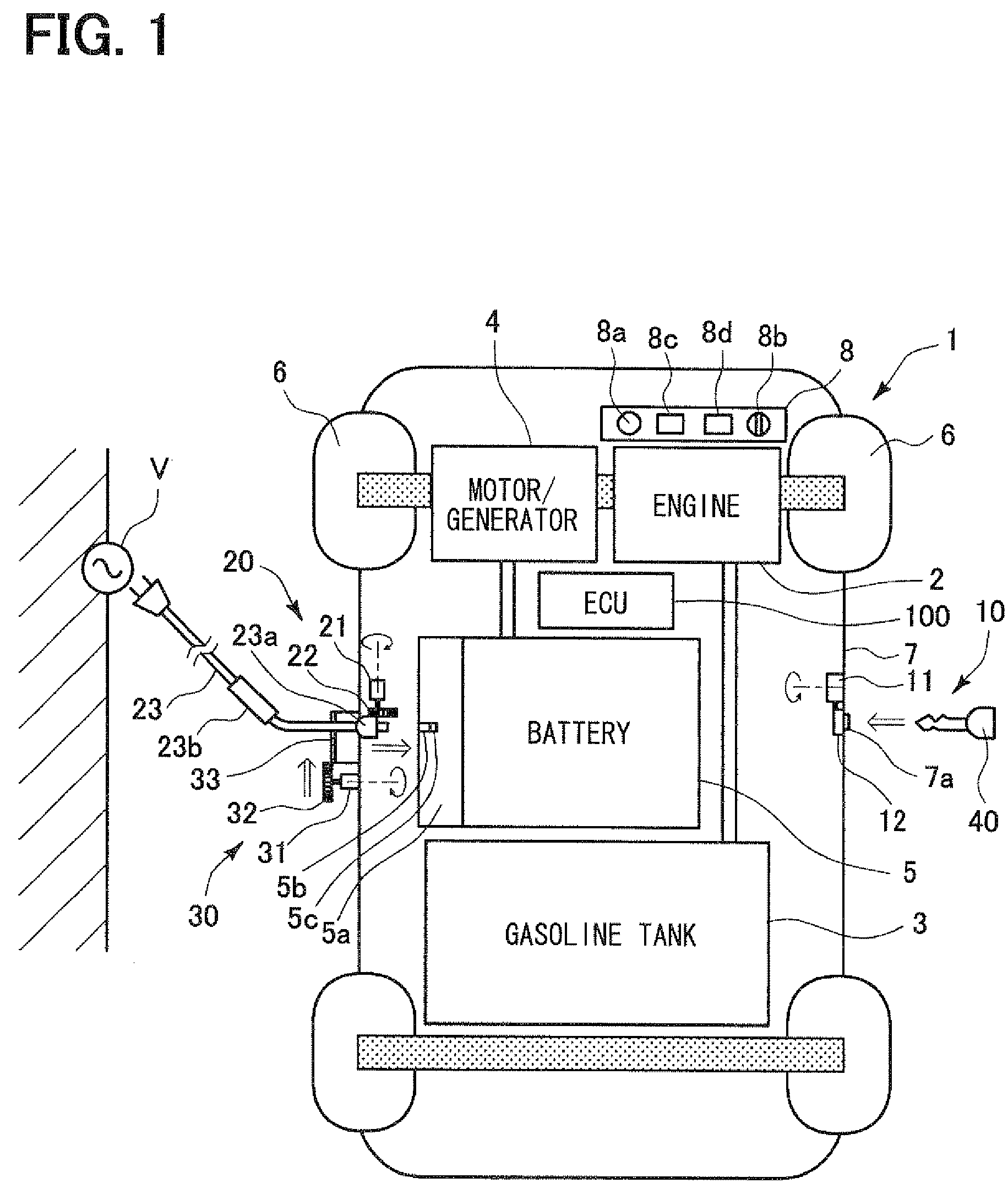
[0034]Embodiments of the invention will be described below with reference to examples shown in the drawings. FIG. 1 shows an example of a plug-in hybrid vehicle (PHV) including a charging system in accordance with an embodiment. The PHV 1 shown in FIG. 1 can use an onboard battery 5 as a source of running power for driving wheels 6. In other words, when the PHV 1 is started or run at a high speed, a fuel in a tank 3, that is, gasoline is burned mainly within an engine 2 in order to rotate the driving wheels 6. At such a time, a motor / generator 4 functions as a generator using the rotary energy of the engine 2 so as to charge the battery 5. On the other hand, when the PHV is run at a low speed in an urban area or the like, the motor / generator 4 functions as a motor using the battery 5 as an energy source. Therefore, the PHV 1 is run mainly as an electric motorcar.

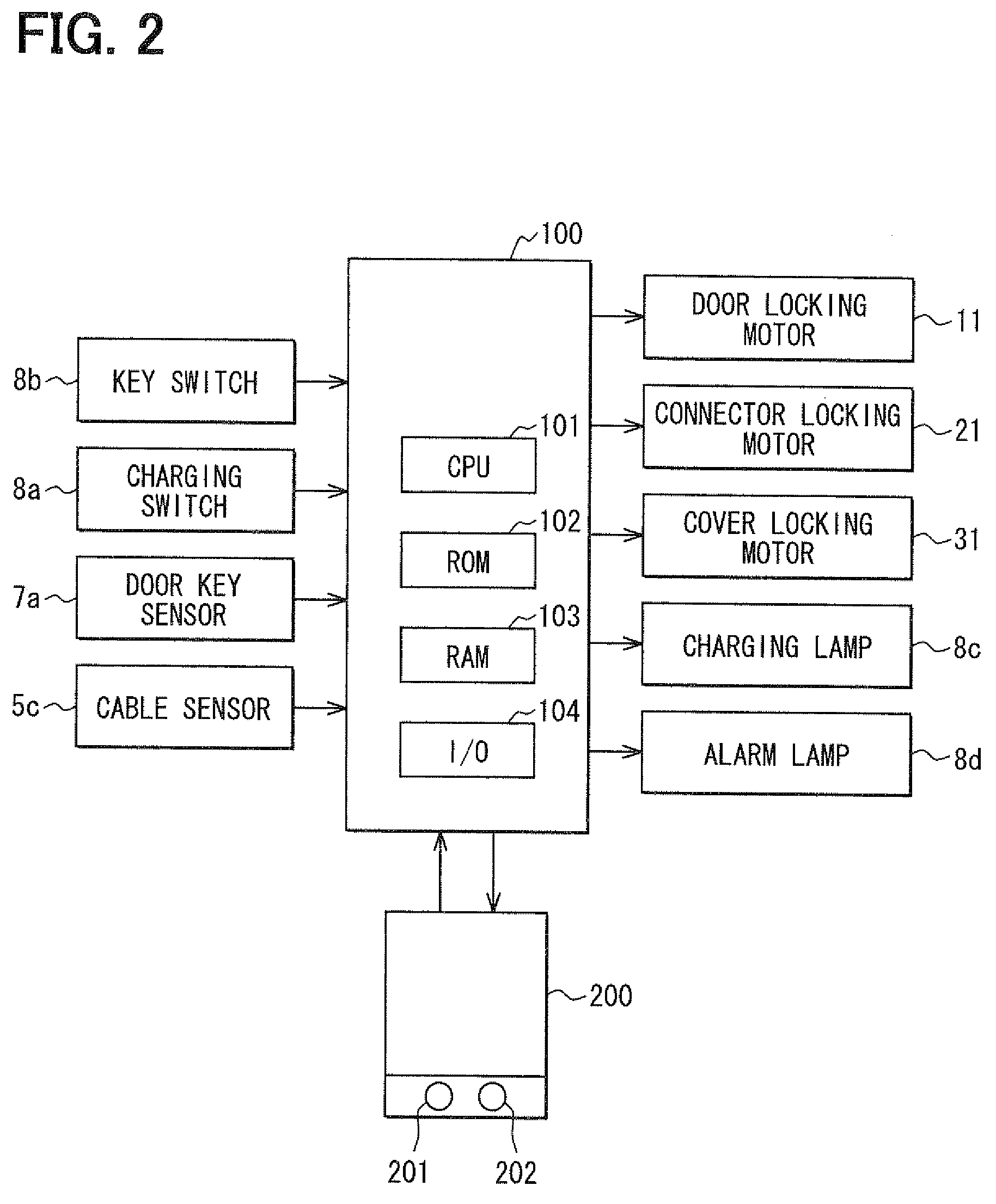
[0035]The PHV 1 includes a door locking mechanism 10, and a connector locking mechanism 20 and a cover locking mechanism 3...

second embodiment

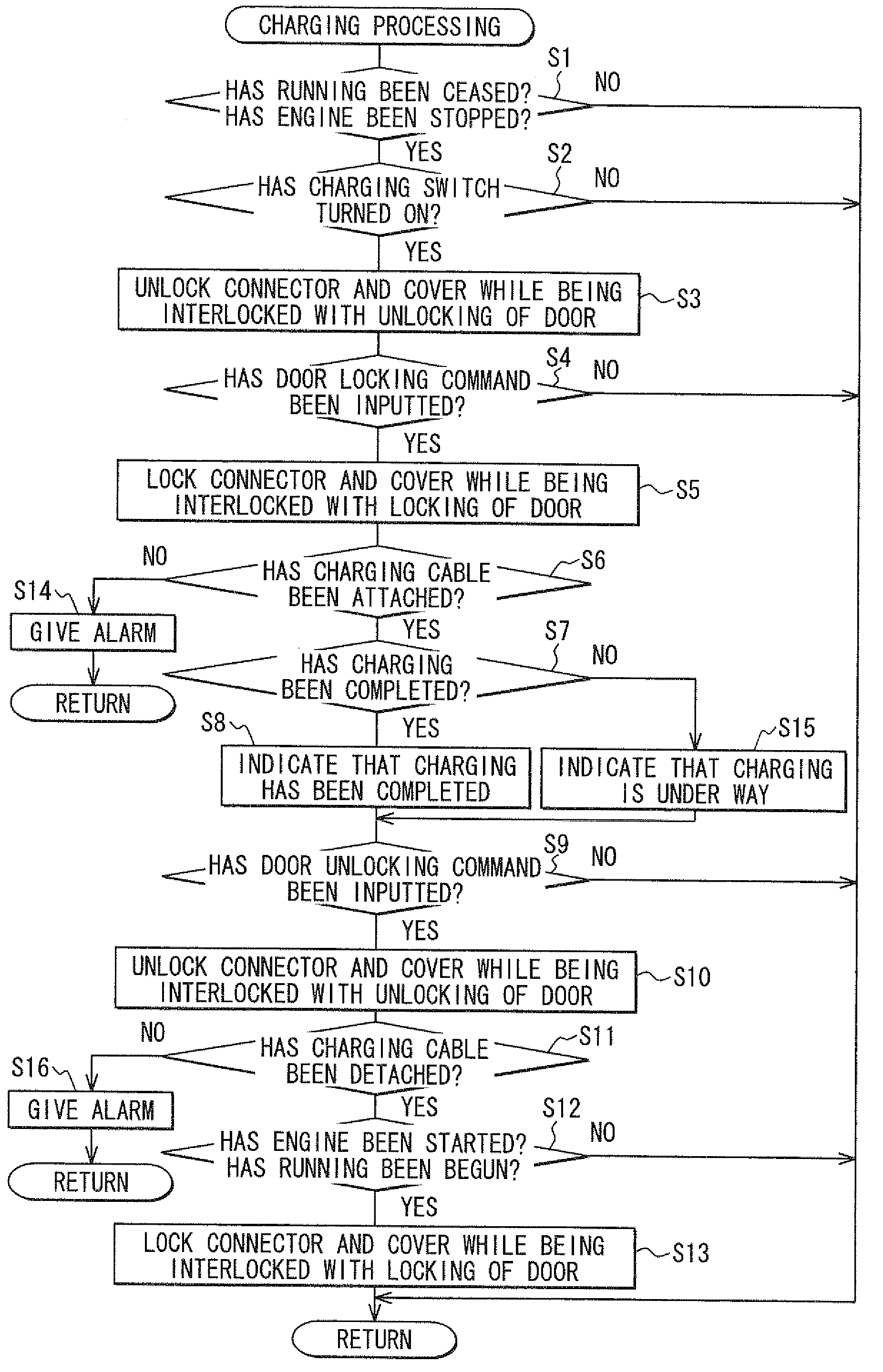
[0053]FIG. 4A and FIG. 4B are flowcharts describing other examples of charging processing and presenting modified parts of the charging processing described in FIG. 3. In FIG. 4A, it is determined whether the door locking command, that is, the door locking signal sent from the key 40 or door key sensor 7a has been inputted for the first time at S41. If the door locking signal has been inputted for the first time, corresponding to YES at S41, the door locking motor 11 is driven in order to lock the door locking mechanism 10 alone at S51. Thereafter, it is determined whether the door locking command has been inputted for the second time, that is, the door locking signal sent from the key 40 or door key sensor 7a, at S42. If the door locking signal has been inputted for the second time, corresponding to YES at S42, the connector motor 21 and cover motor 32 are driven at S52 in order to lock the connector locking mechanism 20 and cover locking mechanism 30 in the same manner as when the...


PUM


Abstract

A charging system provided for vehicles prevents theft of a charging cable, insertion of foreign matter into a vehicle-side receptacle, or tampering when an onboard battery usable for running power is charged from a household power supply. A cable connector of the charging cable is opposed to the vehicle-side receptacle in a connecting part to prepare for charging. When a PHV is exited, a switching command switching from an unlocked state of a door locking mechanism to a locked state is inputted to a PHV ECU responsive to an inputting manipulation performed on a key or door key sensor. The PHV ECU allows the door locking mechanism to switch from the unlocked state to the locked state. The PHV ECU allows locking mechanisms to switch from the unlocked states to the locked states in the manner interlocked with the switching action of the door locking mechanism.

Description

CROSS REFERENCE TO RELATED APPLICATIONS[0001]The present application is based on and claims priority to Japanese Application No. 2007-247892 filed Sep. 25, 2007, the entire contents of which are incorporated herein by reference.BACKGROUND OF THE INVENTION[0002]1. Field of the Invention[0003]The present invention relates to a charging system for vehicles and, more specifically, to using an onboard battery for running power.[0004]2. Description of the Related Art[0005]In recent years, electric vehicles (EVs) and hybrid vehicles (HVs) capable of using an onboard battery for running power have attracted attention from the viewpoint of protection of the global environment through reduction in a carbon-dioxide (CO2) emission, and have been used in practice. Recently, development is under way of a plug-in hybrid vehicle (PHV) whose battery can be charged not only with the rotation of an engine made while the vehicle is running, but from a household power supply or the like at night or duri...

Claims


Application Information

Patent Timeline
Patent Type & Authority Applications(United States)
IPC IPC(8): B60L3/00E05B65/12B60L11/18B60R99/00
CPCB60K6/48Y02T10/70B60L11/1818B60L11/1824B60L11/1838B60L2230/12B60L2240/80B60L2250/10B60L2270/34B60W10/26B60W20/00B60W2540/06Y02T10/6221Y02T10/6269Y02T10/7005Y02T10/7077Y02T10/7088Y02T90/121Y02T90/128Y02T90/14Y02T90/163B60L2270/32B60L11/14B60W2050/143B60L50/16B60L53/16B60L53/18B60L53/60Y02T10/62Y02T10/7072Y02T90/12Y10T70/5889B60W20/13Y02T90/16
Inventor TANAKA, YASUHIRO
Owner DENSO CORP
Why Eureka
Try Eureka