Method for the production of profiled floor elements from a timber material

a technology of timber material and profiled floor, which is applied in the direction of building components, building repairs, wood working apparatuses, etc., can solve the problems achieve the effect of increasing the volume to be machined away, increasing the inherent strength, and increasing the resultant utilisation of materials

Inactive Publication Date: 2009-04-02
NEUHOFER MARTIN
View PDF2 Cites 1 Cited by
  • Summary
  • Abstract
  • Description
  • Claims
  • Application Information

AI Technical Summary

Benefits of technology

[0006]For this purpose, provision can be made for the connecting land of the pre-profiled element to connect the spatially separated longitudinal edges of the covering flange and for the covering layer extending across and beyond the wedge-shaped recess between the rounded longitudinal edges of the covering flange to be adhesively bonded to the pre-profiled element before the covering layer is severed in the wedge-shaped recess to form strips and is pressed against and adhesively bonded to the rounded longitudinal edges in a stripwise manner. Adhesively bonding a covering layer which is common to the profiled floor elements to be created onto the pre-profiled element in a bridging manner provides simpler conditions for attaching the covering layer. However, provision must be made for a gap between the sides of the abutting longitudinal edges by widening the connecting land accordingly to ensure a sufficiently wide edge area between these longitudinal edges for the individual strips produced so that each of the individual longitudinal edge curvatures is covered after the covering layer has been severed in the area of the wedge-shaped recess. However, widening the connecting land increases the volume to be machined away.
[0007]If the greater resultant utilisation of material is to be avoided, the strips of the covering layer can be glued to eac

Problems solved by technology

However, widening the connecting land i

Method used


Image

  • Method for the production of profiled floor elements from a timber material
  • Method for the production of profiled floor elements from a timber material
  • Method for the production of profiled floor elements from a timber material

Examples


Embodiment Construction

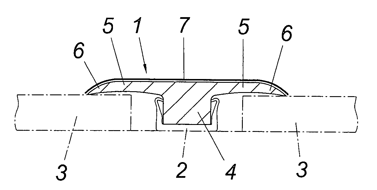
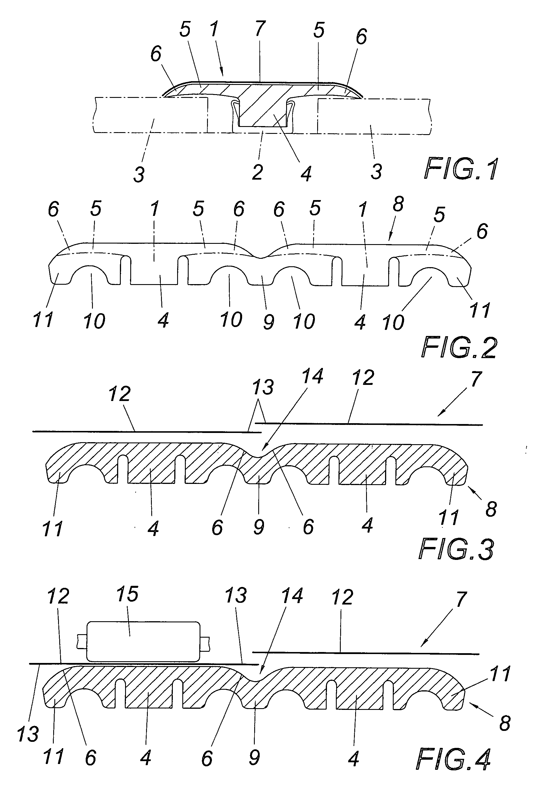
[0020]The profiled floor element 1 to be produced in accordance with the embodiment shown in FIG. 1 is provided with a footing 4 that can be inserted into a floor track 2 in the gap between two floor elements 3 and a covering flange 5 projecting from this footing 4 which laps over the abutting floor elements 3. The visible side of the covering flange 5 is provided with a covering layer 7 extending over its rounded longitudinal edges 6 which can consist of a decorative film, a laminate, a veneer or similar and is adhesively bonded to the visible side of the covering flange 5.

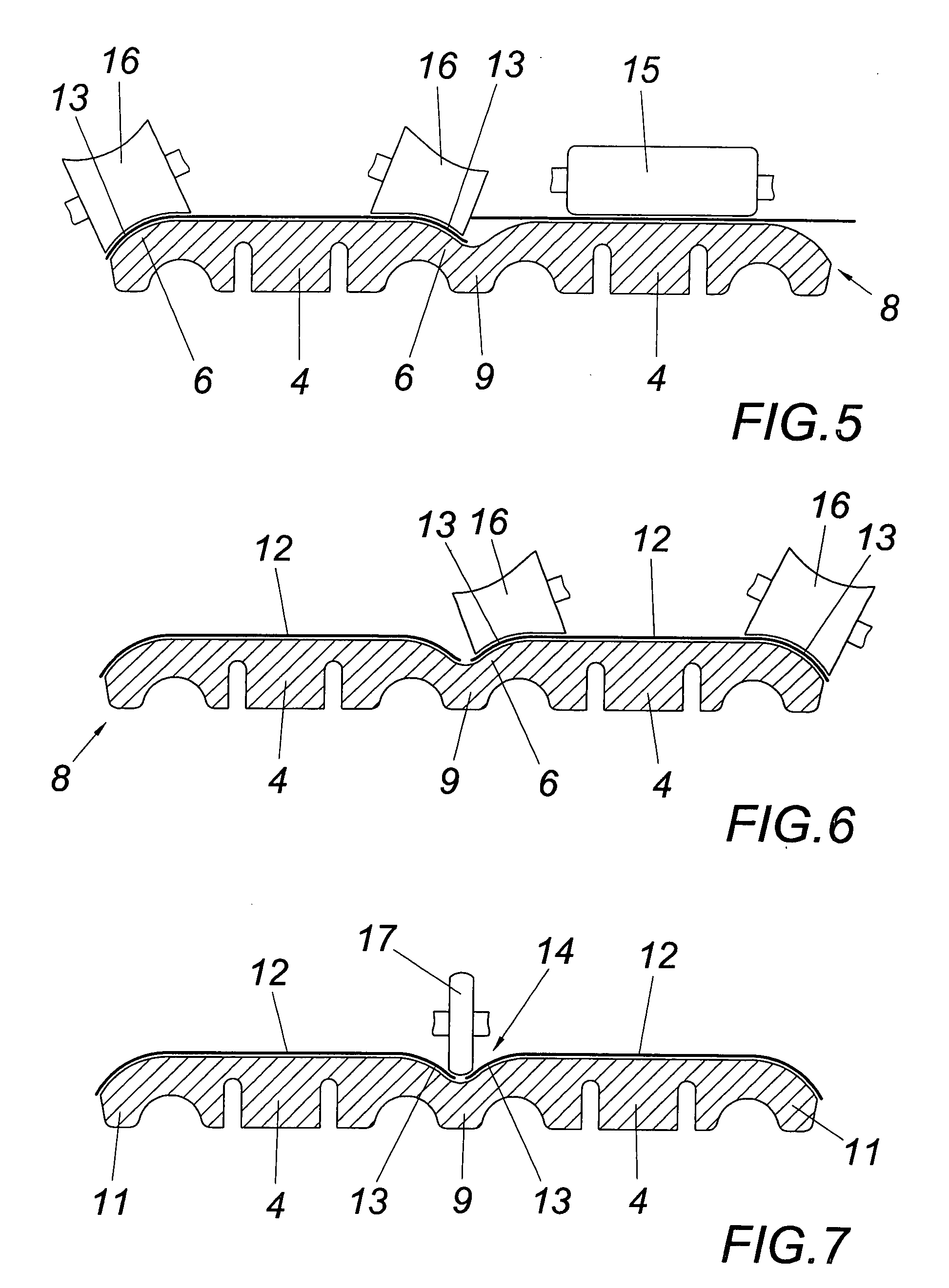
[0021]The production of such a profiled floor element 1 proceeds from a pre-profiled element 8 consisting of a timber material as shown in FIG. 2. This pre-profiled element 8 encompasses two profiled floor elements 1 which abut in the region of their rounded longitudinal edges 6 and which are bridged by a connecting land 9 on the underside of the covering flange 5 facing away from the visible side, with said land...


PUM


Abstract

A method is described for the production of profiled floor elements from a timber material, comprising at least one covering flange protruding from a footing and having a rounded longitudinal edge, with the method proceeding on the basis of a pre-profiled floor element consisting of profiled floor elements connected along a longitudinal edge by means of a connecting land and the profiled floor elements being separated from each other by machining the connecting land on the profiled side opposing the visible side once a covering layer has been adhesively bonded to the pre-profiled floor element in the region of the visible sides of the subsequent profiled floor elements. In order to ensure advantageous production conditions, it is proposed that the strips of the covering layer corresponding to the individual profiled floor elements are adhesively bonded to the pre-profiled floor element, which forms a connecting land bridging the wedge-shaped recess between the rounded longitudinal edges on the side of the covering flange facing away from the visible side, and that the edge sections of the strips, which face each other and protrude into the wedge-shaped recess, are bent into the wedge-shaped recess between the rounded longitudinal edges of the covering flange and are adhesively bonded to the longitudinal edges before the connecting land is machined away on the underside of the covering flange.

Description

1. FIELD OF THE INVENTION[0001]The invention relates to a method for the production of profiled floor elements from a timber material. Said elements are provided with at least one covering flange that has a rounded longitudinal edge and projects from a footing. Said method commences with a pre-profiled element consisting of profiled floor elements connected to each other along a longitudinal edge by means of a connecting land. The profiled floor elements are separated from each other after a covering layer is adhesively bonded to the pre-profiled element in the area of the visible sides of the subsequent profiled floor elements by machining the connecting land on the side of the profiled element facing away from the visible side.2. DESCRIPTION OF THE PRIOR ART[0002]In order to reduce the production effort for the manufacture of profiled covering strips coated on the visible side, a method is known (EP 0 862 976 A1) which proceeds on the basis of a pre-profiled element that correspon...

Claims


Application Information

Patent Timeline
IPC IPC(8): E04B5/00
CPCB27M3/08E04F19/065E04F19/062E04F19/061
Inventor NEUHOFER, MARTIN
Owner NEUHOFER MARTIN
Why Eureka
Try Eureka