Spinning Rotor

a spinning rotor and spindle technology, applied in the field of spinning rotors, to achieve the effect of reducing the run-up time of the rotor, cost saving per machine, and reducing the energy consumption of the spinning station

Inactive Publication Date: 2009-04-02
SAURER GERMANY GMBH & CO KG
View PDF9 Cites 6 Cited by
  • Summary
  • Abstract
  • Description
  • Claims
  • Application Information

AI Technical Summary

Benefits of technology

[0017]Furthermore, it is conceivable, to further reduce the rotor run-up time until the desired rotational operating speed of the spinning rotor is reached in that the wall thickness of the rotor cup, in particular the wall thickness of the slide wall, is correspondingly reduced. The slide wall expediently has a wall thickness d, which is in the range of 0.5 mm≦d≦1.5 mm, preferably in the range of 0.6 mm≦d≦0.8 mm. By means of improving measures of this type, the energy consumption per sp...

Problems solved by technology

The aforementioned connections between the rotor cup and rotor shaft in total have the disadvantage that either the connection is relatively heavy, which has a very disadvantageous effect on the acceleration capacit...

Method used


Image

  • Spinning Rotor
  • Spinning Rotor

Examples


Embodiment Construction

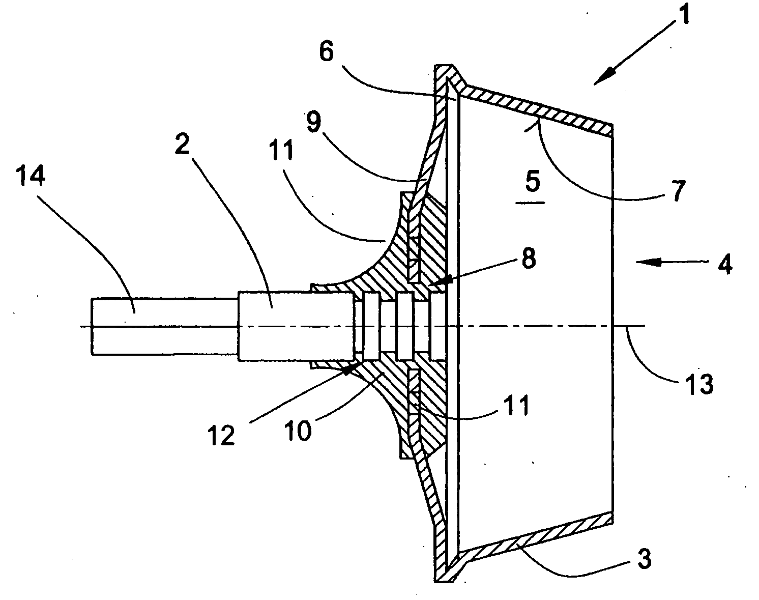
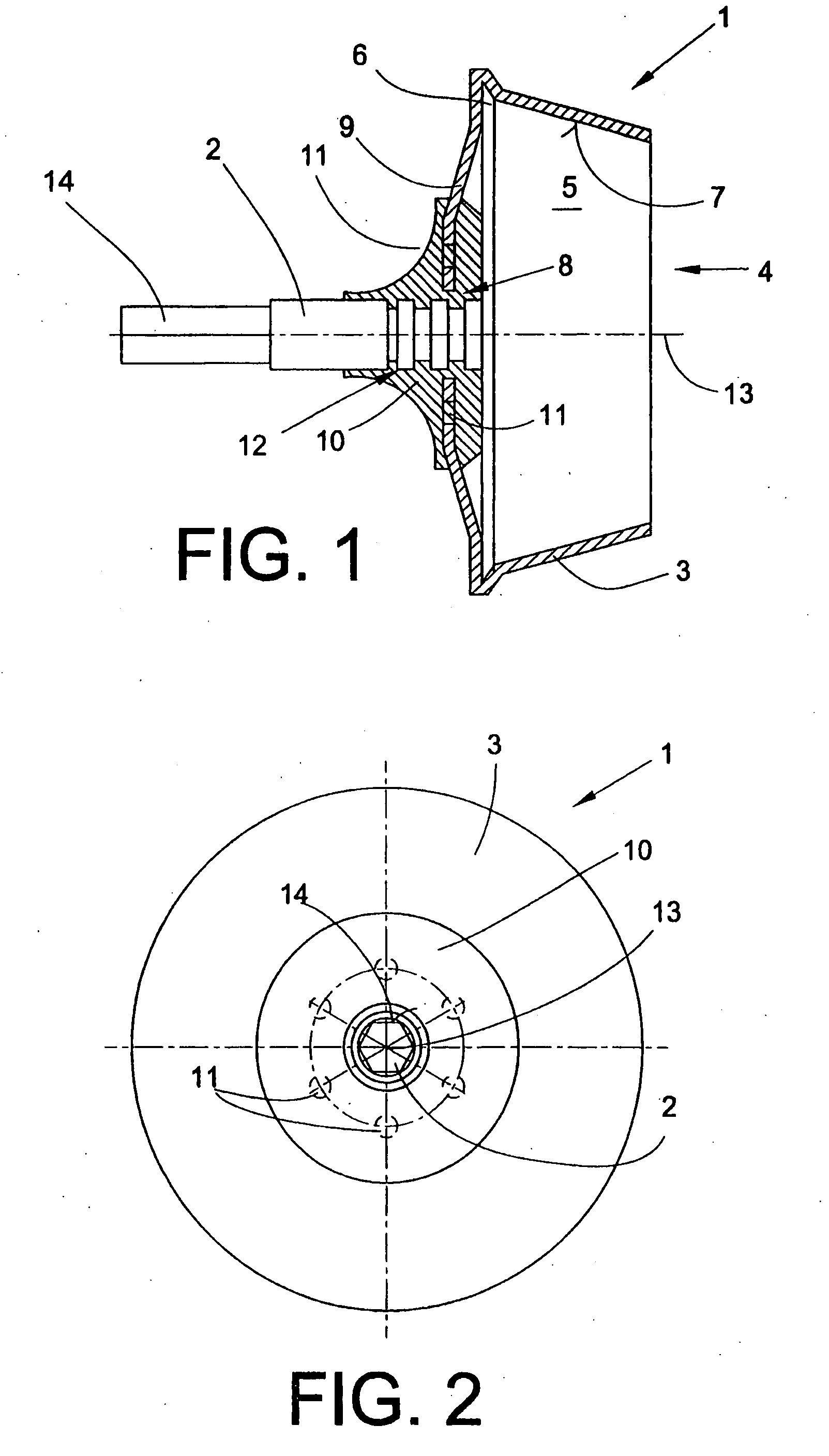
[0022]FIG. 1 shows a spinning rotor 1 of an open end rotor spinning machine which is known per se and therefore not shown explicitly. As described in relative detail, for example in EP 0 972 868 A2, such open end rotor spinning machines, in each case, have a rotor housing which can be subjected to reduced pressure, in which the rotor cup 3 of the spinning rotor 1 rotates at a high rotational speed about its central axis 13.

[0023]The spinning rotor 1 is in this case driven, for example, by an electric motor single drive. The spinning motor 1 is supported, in this case by its rotor shaft, in a magnetic bearing arrangement, not shown, which fixes the spinning rotor 1 both radially and axially.

[0024]In order to be able to dismantle spinning rotors 1 of this type if necessary, in particular the rotor cups 3 subjected to wear, it is known to configure the rotor shafts of spinning rotors of this type in two parts. In other words, the rotor shafts of spinning rotors of this type, as shown i...


PUM

PropertyMeasurementUnit
Lengthaaaaaaaaaa
Lengthaaaaaaaaaa
Lengthaaaaaaaaaa

Abstract

Spinning rotor (1) for an open end rotor spinning machine comprising a rotor shaft (2), a rotor cup (3), which has an opening (4), an inner chamber (5), a rotor groove (6), a conically widening slide wall (7) extending from the opening (4) to the rotor groove (6) and a rotor base (9) arranged opposing the opening (4) and designed with a bore (8), through which the rotor shaft (2) extends at least partially. The rotor shaft (2) is connected by means of a connection element (10) to the rotor cup (3) and the rotor shaft (2) and rotor cup (3) comprise a common rotational axis (13). The rotor shaft (2) and the rotor cup (3) have connection means (11, 12), which are at least partially surrounded by the connection element (10) configured as a cast part, so a positive connection of the rotor shaft (2) to the rotor cup (3) can be achieved.

Description

CROSS-REFERENCES TO RELATED APPLICATIONS[0001]This application claims the benefit of German patent application 10 2005 021 920.9, filed May 12, 2005, herein incorporated by reference.BACKGROUND OF THE INVENTION[0002]The invention relates to a spinning rotor for an open end rotor spinning machine, particularly a spinning rotor comprising a rotor shaft, a rotor cup having an opening, an inner chamber, a rotor groove, a conically widening slide wall extending from the opening to the rotor groove and a rotor base arranged opposing the opening and designed with a bore, through which the rotor shaft extends at least partially, wherein the rotor shaft is connected by means of a connection element to the rotor cup and the rotor shaft and rotor cup comprise a common rotational axis.[0003]In conjunction with open end rotor spinning machines, a large number of the most varied spinning rotors are known from the patent literature and generally consist of a rotor shaft for mounting the spinning r...

Claims


Application Information

Patent Timeline
IPC IPC(8): D01H4/10
CPCD01H4/10
Inventor WASSENHOVEN, HEINZ-GEORG
Owner SAURER GERMANY GMBH & CO KG
Why Eureka
Try Eureka