Scribing Methods for Photovoltaic Modules Including a Mechanical Scribe

a technology of photovoltaic modules and mechanical scribes, which is applied in the direction of photovoltaic modules, electrical devices, semiconductor devices, etc., can solve the problems of difficult to create narrow grooves between solar cells, problems known to occur when scribing photovoltaic modules,

Inactive Publication Date: 2009-04-02
SOLYNDRA RESIDUAL TRUST
View PDF10 Cites 32 Cited by
  • Summary
  • Abstract
  • Description
  • Claims
  • Application Information

AI Technical Summary

Problems solved by technology

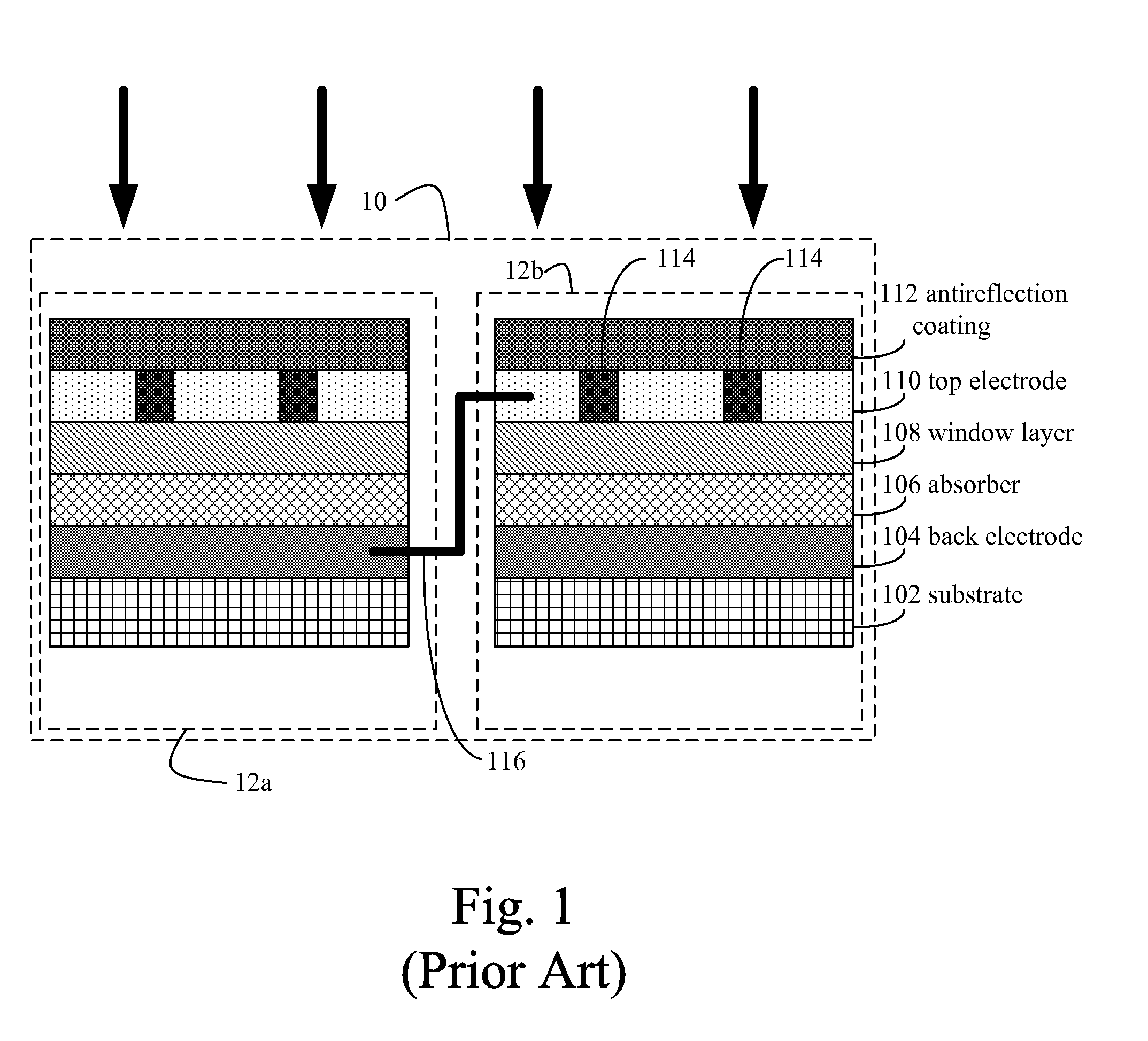
However, even when a TCO layer is present, a bus bar network 114 is typically needed in conventional photovoltaic modules 10 to draw off current since the TCO has too much resistance to efficiently perform this function in larger photovoltaic modules.
This is because hard or brittle materials often break or shatter during mechanical scribing, making it difficult to create narrow grooves between solar cells.
Despite the advantages of laser scribing, problems are known to occur when scribing photovoltaic modules in order to form solar cells 12.
However, in this arrangement, the photovoltaic module is only supported at the ends and not in the middle.
This results in an uneven cut in the photovoltaic module since the scriber is sensitive to changes in the spacing between the stationary scriber and the surface of the photovoltaic module.
Such uneven cuts are undesirable, particular since some layers of the photovoltaic module must be cut precisely.
For example, uneven cuts can destroy the functionality of the cells.
If the distance between the scribe and the photovoltaic module changes during scribing, portions of the groove may not be deep enough to cut completely through the layer.
This enhances the undesired shape of the bow, resulting in even larger variances in the spacing between the photovoltaic module and the scriber during rotation.
For example, a distance change of three millimeters (mm) between the surface of the photovoltaic module and the scriber during rotation can result in fatal defects in the design of the photovoltaic module.
Rotating the photovoltaic module around a vertical axis would eliminate the static bow effect but not the rotational bow effect, and would also increase the difficulty of designing an effective scribing system.

Method used


Image

  • Scribing Methods for Photovoltaic Modules Including a Mechanical Scribe
  • Scribing Methods for Photovoltaic Modules Including a Mechanical Scribe
  • Scribing Methods for Photovoltaic Modules Including a Mechanical Scribe

Examples


Embodiment Construction

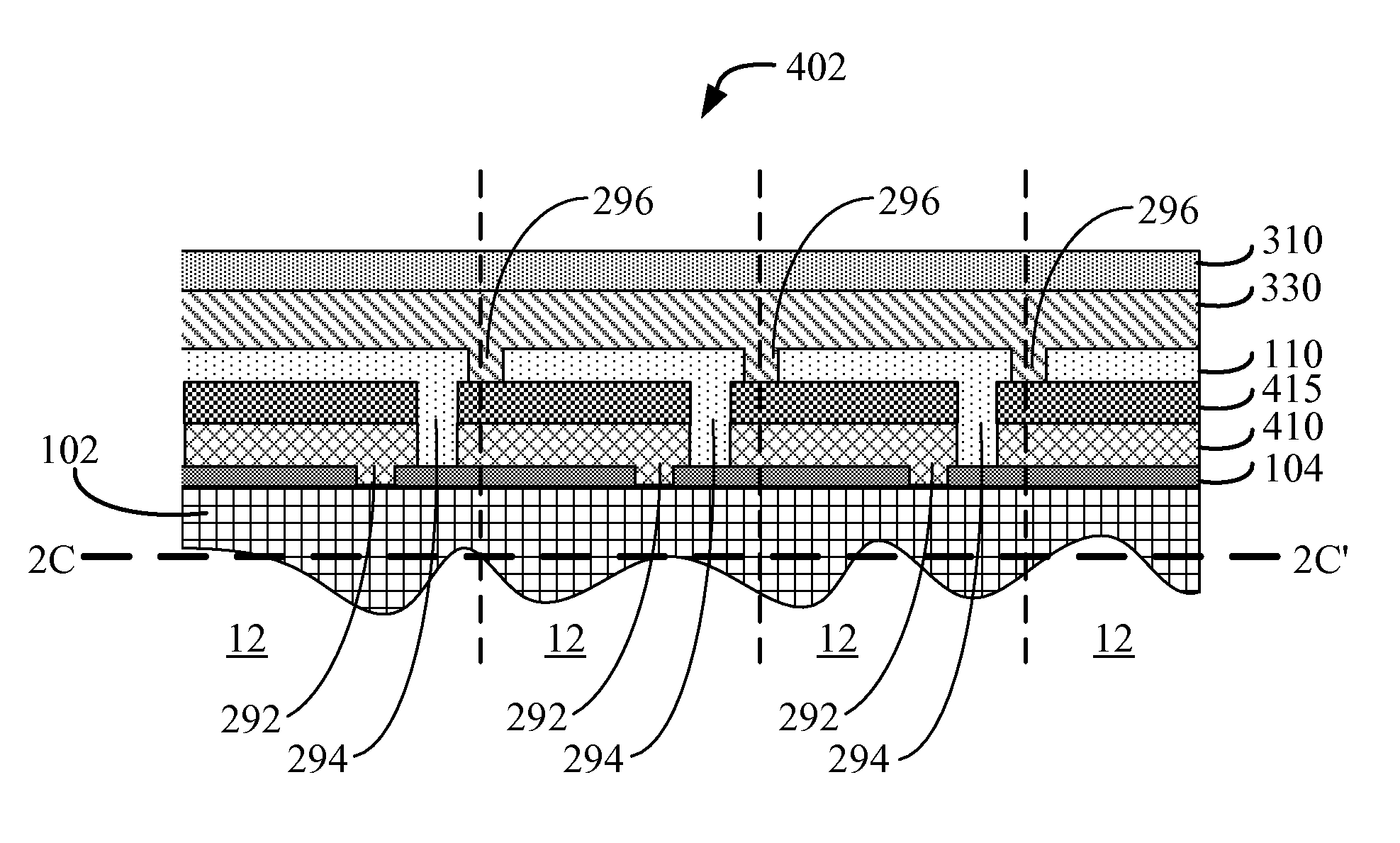
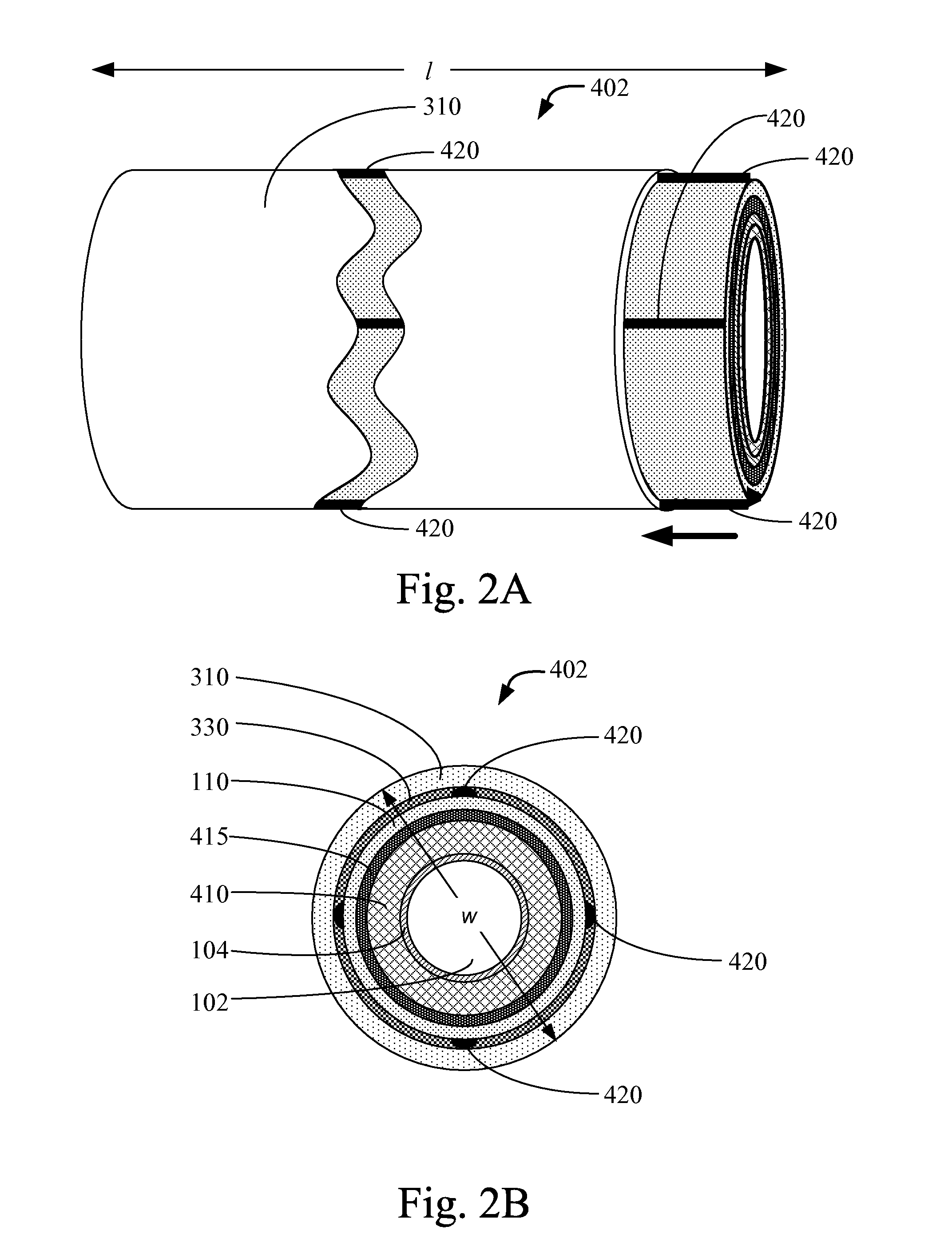
[0022]Disclosed herein are systems and methods for mechanical and laser scribing. Such systems and methods can be used for a wide range of applications such as for manufacturing non-planar solar cells of photovoltaic modules. More generally, the systems and methods disclosed herein can be used to facilitate a broad array of micromachining techniques including microchip fabrication. Micromachining (also termed microfabrication, micromanufacturing, micro electromechanical machining) refers to the fabrication of devices with at least some of their dimensions in the micrometer range. See, for example, Madou, 2002, Fundamentals of Microfabrication, Second Edition, CRC Press LLC, Boca Raton, Fla., which is hereby incorporated by reference herein in its entirety for its teachings on microfabrication. Microchip fabrication is also disclosed in Van Zant, 2000, Microchip Fabrication, Fourth Edition, McGraw-Hill, New York, which is hereby incorporated by reference herein in its entirety for it...


PUM


Abstract

Methods for forming photovoltaic modules, and the photovoltaic modules produced by such methods are provided. A back-electrode layer is disposed on an elongated substrate. A first patterning is performed on the back-electrode layer using a laser scriber or a mechanical scriber. A semiconductor junction layer is disposed on top of the back-electrode layer. A second patterning is performed on the semiconductor junction layer using a mechanical scriber. A transparent conductor layer is disposed on top of the semiconductor junction layer. A third patterning is performed on the transparent conductor layer using a mechanical scriber thereby forming at least a first solar cell and a second solar cell, where the first solar cell and the second solar cell each comprise an isolated portion of the back-electrode layer, the semiconductor junction layer, and the transparent conductor layer.

Description

CROSS REFERENCE TO RELATED PATENT APPLICATION[0001]This application claims priority to U.S. Provisional Patent Application No. 60 / 976,401, filed on Sep. 28, 2007, which is hereby incorporated by reference herein in its entirety.1. FIELD OF THE APPLICATION[0002]This application relates to using mechanical scribing techniques as applied to photovoltaic modules and photovoltaic modules produced by such techniques.2. BACKGROUND OF THE APPLICATION[0003]The solar cells of photovoltaic modules are typically fabricated as separate physical entities with light gathering surface areas on the order of 4-6 cm2 or larger. For this reason, it is standard practice for power generating applications to mount photovoltaic modules containing one or more solar cells in a flat array on a supporting substrate or panel so that their light gathering surfaces provide an approximation of a single large light gathering surface. Also, since each solar cell itself generates only a small amount of power, the req...

Claims


Application Information

Patent Timeline
Patent Type & Authority Applications(United States)
IPC IPC(8): H01L31/042H01L31/18
CPCH01L31/022466H01L31/0296H01L31/0304H01L31/0322H01L31/046H01L31/073H01L31/0735H01L31/18Y02E10/50H01L31/072H01L31/0463
Inventor MILSHTEIN, ERELBULLER, BENYAMIN
Owner SOLYNDRA RESIDUAL TRUST
Why Eureka
Try Eureka