Light source and projector

a technology of projectors and light sources, applied in the field of light sources, can solve the problems of shortening the life of the electrodes, and achieve the effect of less flicker or flickering and good images

Inactive Publication Date: 2009-04-02
SEIKO EPSON CORP
View PDF8 Cites 15 Cited by
  • Summary
  • Abstract
  • Description
  • Claims
  • Application Information

AI Technical Summary

Benefits of technology

[0006]An advantage of some aspects of the invention is to provide a light source and a projector which incorporating the light source, which can appropriately adjust initial operations before electric power reaches a rated value and a steady operation after reaching the rated value and suppress deterioration of characteristics.
[0008]In the above light source, the initial operation is performed by the drive unit in any one of conditions selected from the plural initial power feeding conditions according to the determination result by the determination unit and the steady operation is performed by the drive unit in any one of conditions selected from the plural steady power feeding conditions according to the determination result by the determination unit, therefore, the initial operation and the steady operation are appropriately executed in accordance with states of the discharge lamp. Accordingly, the light emission state of the discharge lamp can be maintained in a good state with less flicker or the like over a long period of time, which can increase the life of the discharge lamp.
[0011]According to further another aspect of the invention, the plural initial power feeding conditions correspond to plural stages of deterioration of the discharge lamp, in which an current value of the initial power feeding condition corresponding to a higher stage of deterioration of the discharge lamp is smaller than an current value of the initial power feeding condition corresponding to a lower stage of deterioration of the discharge lamp in a period of a starting operation provided at the beginning of the initial operation. In this case, the tendency in which arc discharge is liable to be formed at a sealed portion from needle crystals formed at the root side of the electrodes in the initial operation can be suppressed, which prevents the deterioration of the discharge lamp from proceeding earlier.
[0012]According to further another aspect of the invention, the initial operation includes a rising operation performed after the starting operation, in which the plural initial power feeding conditions corresponds to plural stages of deterioration of the discharge lamp, and an increasing amount of an current value of the initial power feeding condition corresponding to a higher stage of deterioration of the discharge lamp is larger than the increasing amount of an current value of the initial power feeding condition corresponding to a lower stage of deterioration of the discharge lamp at the end of the rising operation period in the initial operations. In this case, even when projections and depressions formed in the vicinity of protrusions at the tip side of electrodes are difficult to be melted by deterioration with time, projections and depressions can be positively melted. It is also possible to suppress the tendency that protruding tip portions are difficult to be grown with time at the steady operation, which prevents deterioration of the discharge lamp from proceeding earlier.
[0013]According to further another aspect of the invention, the plural steady power feeding conditions correspond to plural stages of deterioration of the discharge lamp, in which electric power of the steady power feeding condition corresponding to a higher stage of deterioration of the discharge lamp is larger than electric power of the steady power feeding condition corresponding to a lower stage of deterioration of the discharge lamp, which is supplied in a latter half period of a half cycle in alternating-current power to be supplied to the first electrode and the second electrode respectively. In this case, it is possible to grow or maintain tip portions while projections and depressions formed at the tip portions of the first electrode and the second electrodes are melted at the initial stage. At this time, even when projections and depressions formed at the tip portions of the electrodes are difficult to be melted by deterioration with time, the projections and depressions can be positively melted. It is also possible to suppress the tendency that protruding tip portions are difficult to be grown with time at the steady operation.
[0015]In the above projector, since the above-described light source is used, a projector in which it is not necessary to change the light source for a long period of time and good images are projected can be realized according to the discharge lamp having long life while maintaining the light emitting state of the discharge lamp in a good state with less flicker or the like over a long period of time.

Problems solved by technology

However, the above drive methods are to be performed after electric power reaches a rated value, therefore, there are some cases in which flicker occurs earlier or the life of the electrode is shorten because of insufficient control of the state of the electrode before reaching the rated value.

Method used


Image

  • Light source and projector
  • Light source and projector
  • Light source and projector

Examples


first embodiment

[0028]Hereinafter, a configuration, operations and the like of a light source according to a first embodiment of the invention will be explained with reference to the drawings.

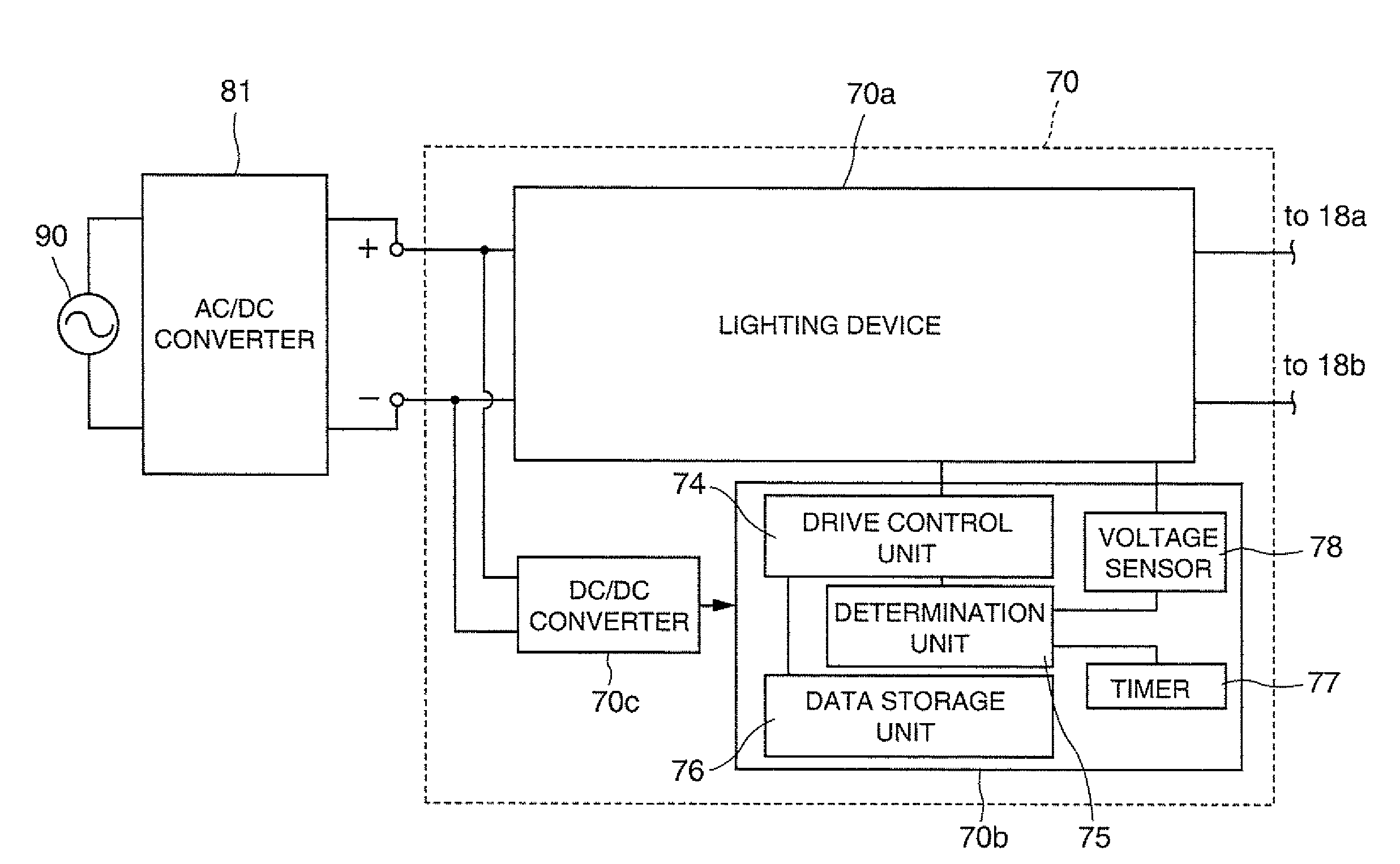
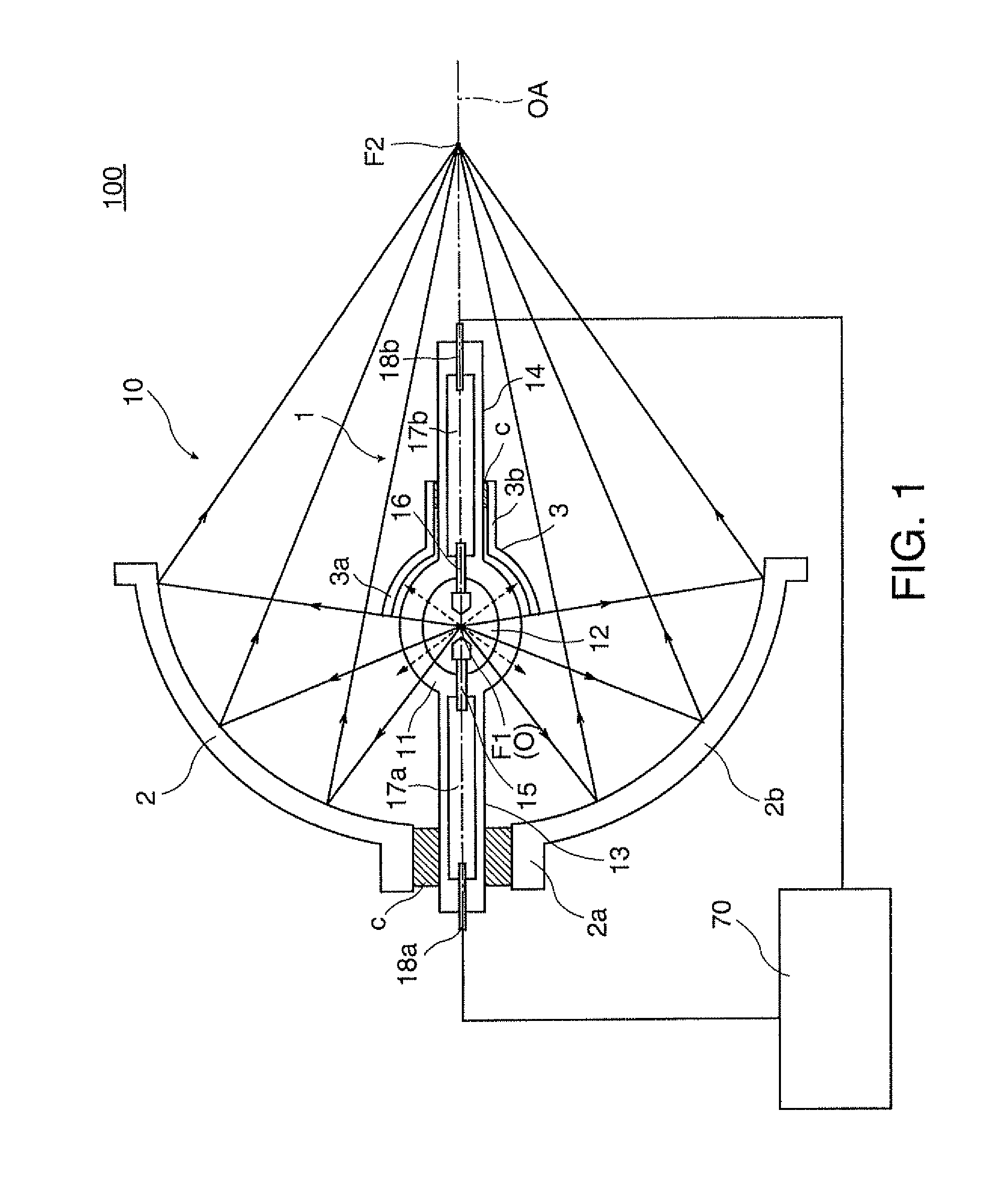
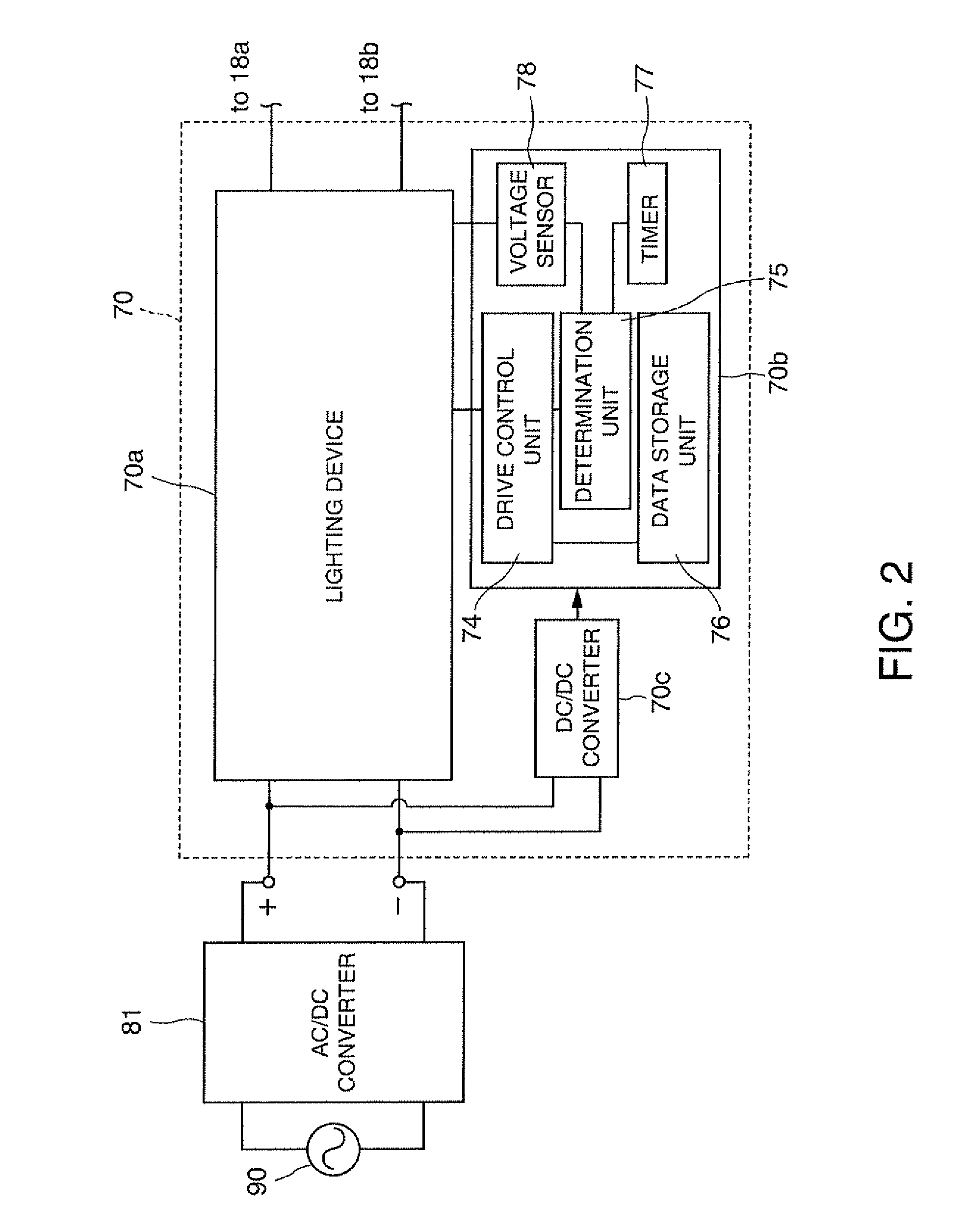
[0029]FIG. 1 is a cross-sectional view conceptually explaining a configuration of a light source 100. In the light source 100, a light source unit 10 which is a discharge lamp includes a discharge light-emission type discharge lamp 1, a reflector 2 which is an oval main reflection mirror and a sub-mirror 3 which is a spherical sub-reflection mirror. A light source driver 70 is an electrical circuit for allowing the light source unit 10 to emit light in a desired state by supplying alternating current to the light source unit 10, which will be described later in detail.

[0030]In the light source unit 10, the discharge lamp 1 is formed by a light-transmissive quarts glass tube the center of which is expanded in a spherical shape, including a body portion 11 which is a sealed body emitting light for illumination a...


PUM


Abstract

A light source includes an discharge lamp including a first electrode and a second electrode emitting light by discharge between them, a drive unit performing a steady operation which supplies steady energy to the first and second electrodes and an initial operation which supplies energy to the first and second electrodes with an operation different from the steady operation before performing the steady operation, a determination unit determining states of the discharge lamp and a data storage unit storing plural initial power feeding conditions provided corresponding to states of the discharge lamp as examples of the initial operation and plural steady power feeding conditions provided corresponding to the states of the discharge lamp as examples of the steady operation, in which the drive unit performs the initial operation in any one of conditions selected from the plural initial power feeding conditions according to a determination result by the determination unit and performs the steady operation in any one of conditions selected from the plural steady power feeding conditions according to a determination result by the determination unit.

Description

BACKGROUND[0001]1. Technical Field[0002]The invention relates to a light source including a discharge lamp which has a pair of electrodes and a projector in which such light source is incorporated.[0003]2. Related Art[0004]The state of a discharge lamp which is incorporated in a discharge light-emitting type light source varies with operating time and, especially, an electrode varies its shape with time because it is consumed during lighting. The crystallization state or an impurity content of tungsten which is a component of the electrode also varies with time. A drive method of adjusting a drive waveform at the steady state by detecting the variation of states as the above by lamp voltage and the like, or a drive method of adjusting a drive waveform according to operating accumulated time by monitoring the operating accumulated time are disclosed. Examples of the related art include WO2004 / 066687, JP-A-2005-276623, JP-A-2004-39563, JP-A-2003-264094, JP-A-2005-310484, and JP-A-2005...

Claims


Application Information

Patent Timeline
Patent Type & Authority Applications(United States)
IPC IPC(8): H05B41/36
CPCY02B20/208H05B41/2928Y02B20/00
Inventor YAMAUCHI, KENTAROTERASHIMA, TETSUOTAKEZAWA, TAKESHIOKAWA, KAZUOKIMURA, KEISHI
Owner SEIKO EPSON CORP
Why Eureka
Try Eureka