Automotive Power Supply System

a power supply system and automotive technology, applied in the direction of electric vehicles, electric devices, battery arrangements, etc., can solve problems that have not yet been solved, and achieve the effect of high level of safety

Active Publication Date: 2009-04-02
HITACHI LTD +1
View PDF4 Cites 87 Cited by
  • Summary
  • Abstract
  • Description
  • Claims
  • Application Information

AI Technical Summary

Benefits of technology

[0011]An object of the present invention is to provide an automotive power supply system assuring a high level of safety.
[0012]The object described above is achieved in the present invention by providing an automotive power supply system comprising a battery module that includes a plurality of serially connected battery groups each constituted with a plurality of serially connected battery cells, a plurality of integrated circuits each disposed in correspondence to one of the battery groups, a control circuit, a transmission path through which the integrated circuits are connected to the control circuit and a relay circuit via which an electrical current is supplied from the battery module. In response to a start signal instructing an operation start and received via the transmission path, each integrated circuit measures terminal voltages at the battery cells in the corresponding battery group and executes an abnormality diagnosis. If abnormality diagnosis results provided by the integrated circuits indicate no abnormality, the control circuit closes the relay, enabling supply of electrical current from the battery module and subsequently the control circuit receives measurement results from the integrated circuits via the transmission path. Since this structure allows the abnormality diagnosis to be executed with priority, power can be supplied quickly.

Problems solved by technology

While it is desirable to supply power to the electrical load as soon as possible in the automotive power supply system structured as described above, there is a safety issue yet to be addressed effectively in that in the event of an abnormality at a battery power may be supplied before the abnormality is detected.

Method used


Image

  • Automotive Power Supply System
  • Automotive Power Supply System
  • Automotive Power Supply System

Examples


Embodiment Construction

[0046]The following is an explanation of an embodiment of the automotive power supply system according to the present invention, given in reference to drawings. The embodiment of the present invention described below assures a high level of safety in a drive system for an automotive rotating electrical machine, in a DC power supply system, in a DC power supply cell controller or in integrated circuits used in a DC power supply cell controller.

[0047]Through the embodiment described below, the following issues are effectively addressed as well as the issues described earlier.

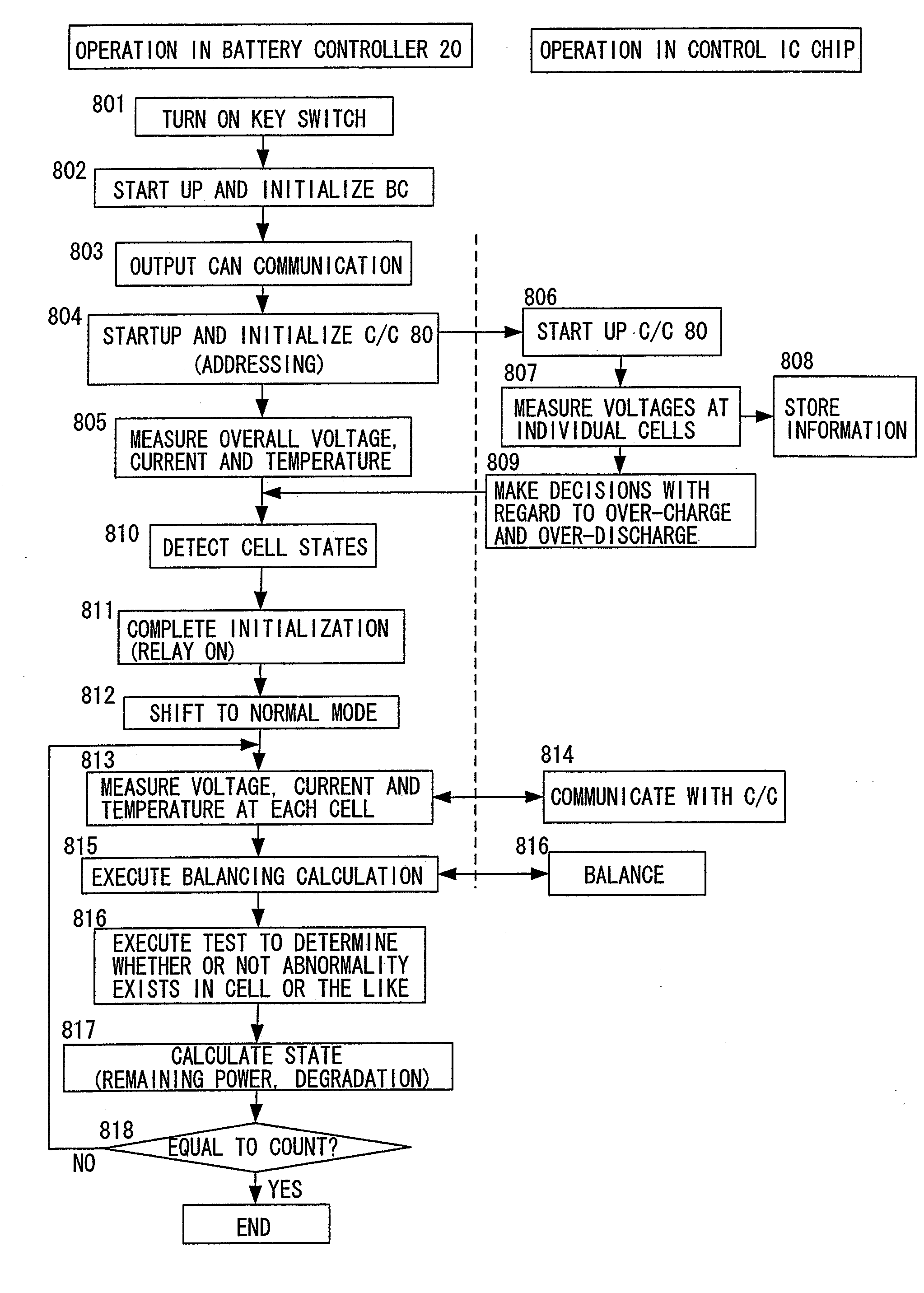
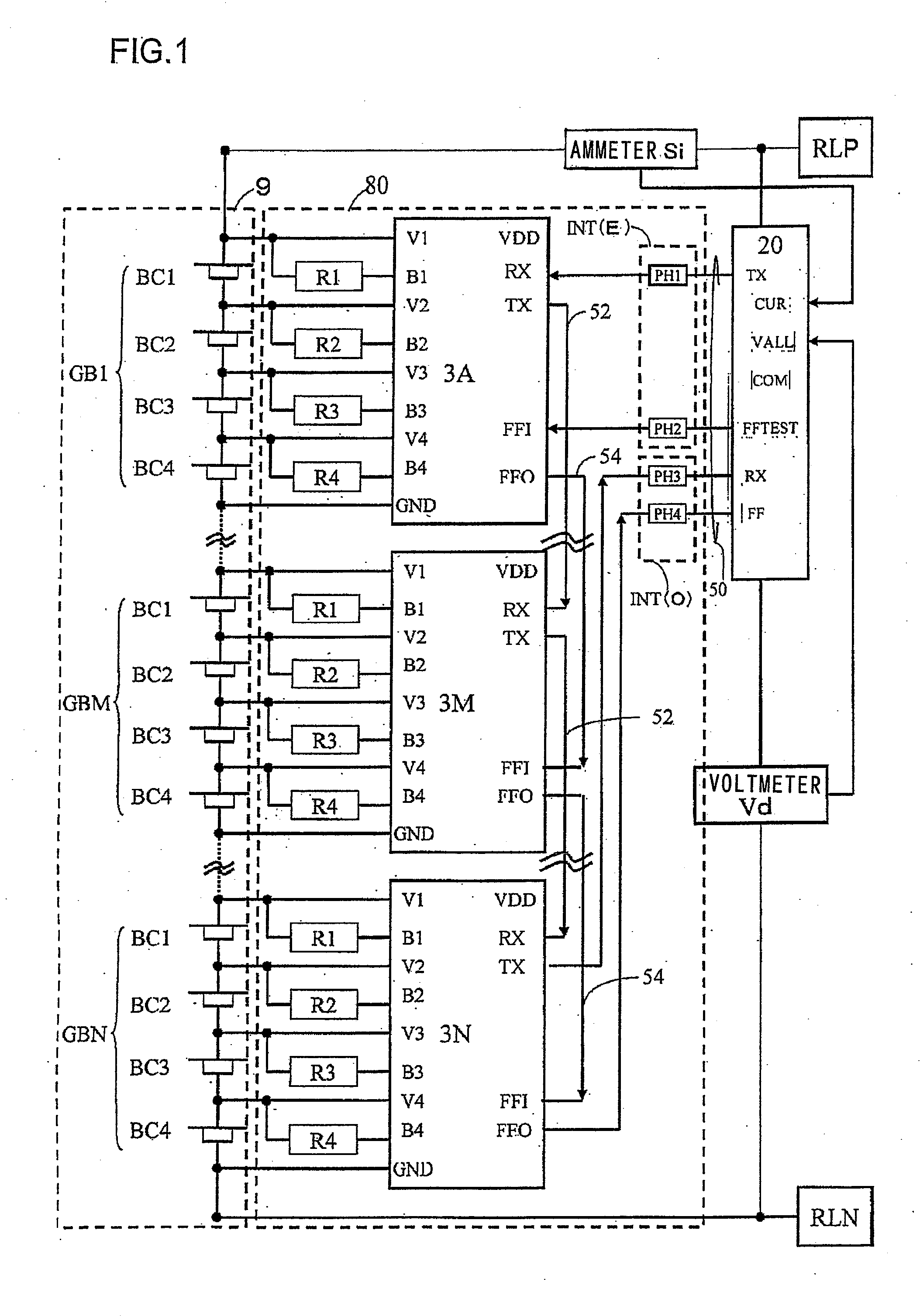
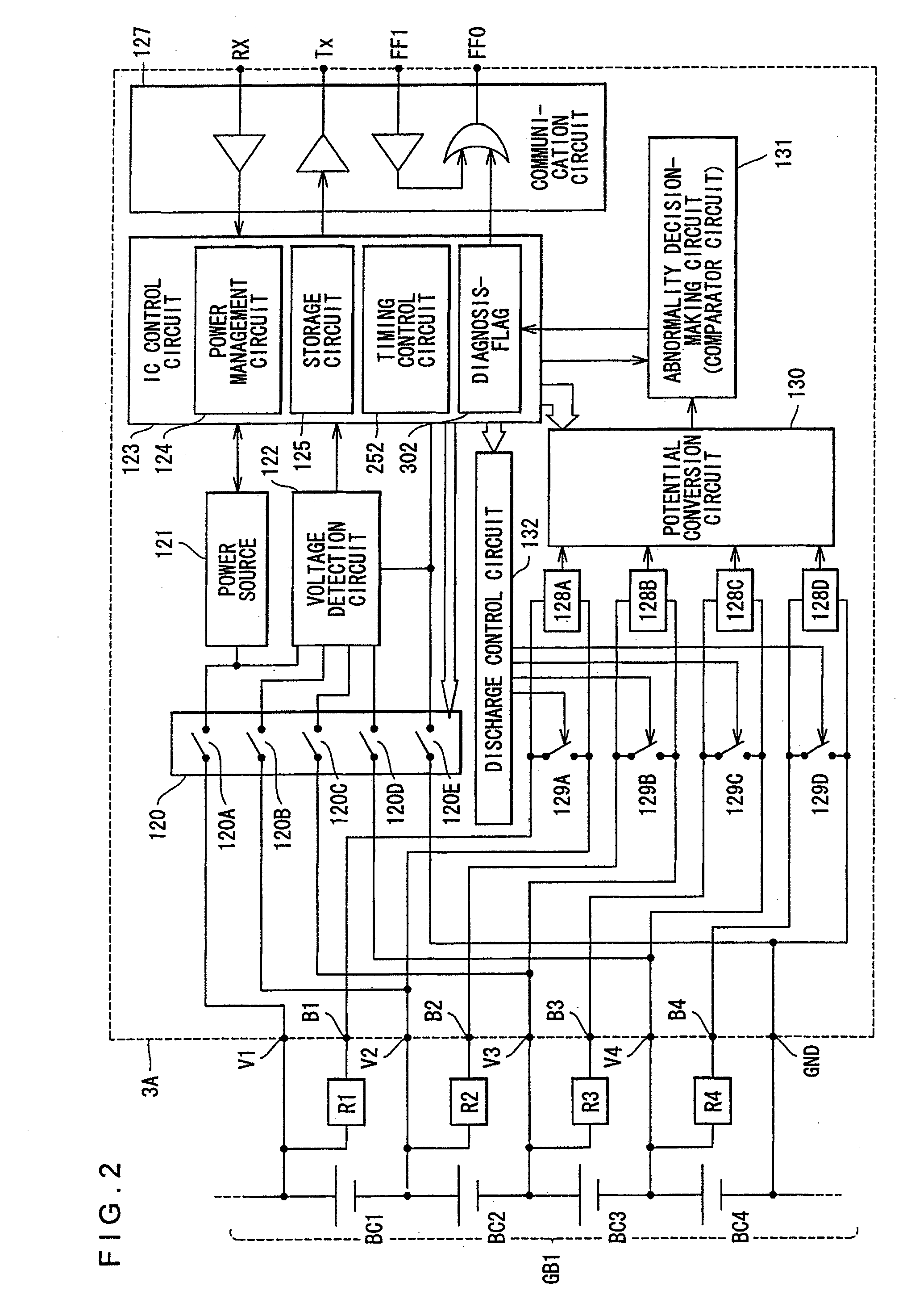
[0048]In the embodiment described below, a diagnosis for a connecting line that connects an integrated circuit that measures a terminal voltage at a battery cell with the battery cell, as well as a diagnosis for the battery cell itself, is executed. These two types of diagnosis are executed independently at each integrated circuit and in the event of an abnormality, the occurrence of the abnormality is reported vi...


PUM


Abstract

An automotive power supply system comprises a battery module that includes serially connected battery groups each constituted with serially connected battery cells, integrated circuits each disposed in correspondence to one of the battery groups, a control circuit, a transmission path through which the integrated circuits are connected to the control circuit and a relay circuit via which an electrical current is supplied from the battery module. In response to a start signal instructing an operation start and received via the transmission path, each integrated circuit measures terminal voltages at the individual battery cells in the corresponding battery group and executes an abnormality diagnosis. If abnormality diagnosis results provided by the integrated circuits indicate no abnormality, the control circuit closes the relay, enabling supply of electrical current from the battery module and subsequently, the control circuit receives measurement results from the integrated circuits via the transmission path.

Description

INCORPORATION BY REFERENCE[0001]The disclosure of the following priority application is herein incorporated by reference:[0002]Japanese Patent Application No. 2007-253649 filed Sep. 28, 2007BACKGROUND OF THE INVENTION[0003]1. Field of the Invention[0004]The present invention relates to an automotive power supply system.[0005]2. Description of Related Art[0006]There are automotive power supply systems known in the related art that include an inverter connected to a rotating electrical machine and a multi-series battery control system.[0007]Such an automotive power supply system is configured so as to charge the individual batteries in the multi-series battery control system, which are connected in series, via the inverter with the power originating from the rotating electrical machine that rotates as the vehicle travels and also to supply power from the batteries to the rotating electrical machine via the inverter.[0008]The voltages at the individual batteries are detected and the SO...

Claims


Application Information

Patent Timeline
Patent Type & Authority Applications(United States)
IPC IPC(8): H02J7/00G08B21/00B60L3/00H02J7/02
CPCB60L3/0046B60L11/1861B60L11/1866B60L2240/545B60L2240/547B60L2240/549Y02T10/7061G01R31/3679H02J7/0013H02J7/0021H02J2007/0067Y02T10/7005Y02T10/7044G01R31/3658G01R31/392G01R31/396B60L58/22B60L58/15B60L58/26B60L58/14H02J7/0025Y02T10/70H02J7/0014H02J7/0048H02J7/005
Inventor EMORI, AKIHIKOKAWAHARA, YOUHEISAKABE, KEIKIKUCHI, MUTSUMIYAMAUCHI, TATSUMIKUDO, AKIHIKO
Owner HITACHI LTD
Why Eureka
Try Eureka