Stereoscopic image display employing solid state light sources

a technology of solid state light source and stereoscopic image, applied in the field of stereoscopic display, can solve the problems of false stereoscopic perception, fatigue to the eye, strong stereoscopic sensation, etc., and achieve the effect of reducing system cost, high efficiency of optical energy use, and reducing cross talk between two stereoscopic channels

Inactive Publication Date: 2009-04-02
SU WEI
View PDF3 Cites 39 Cited by
  • Summary
  • Abstract
  • Description
  • Claims
  • Application Information

AI Technical Summary

Benefits of technology

[0012]The present invention discloses a novel design of a liquid crystal based stereoscopic display system that can highly efficiently use the optical energy from solid light sources and divide the three primary colors of random polarizations each into two orthogonal polarization states, one for the left channel and the other for the right channel. By using a special X cube, the combined full color image beam has a co-linear polarization. In addition, by sharing a number of optical components between the two stereoscopic channels, and by making the optical configuration for each color light path identical, except for the coatings that are designed for the specific color spectral band, the presently disclosed design is not only more compact but also of lower in system cost. Furthermore, by employing a depolarization compensation scheme in a rear projection stereoscopic display, the cross talk between two stereoscopic channels is substantially reduced.
[0013]One object of the invention is to increase the optical energy efficiency of a stereoscopic display system.
[0014]Another object of the invention is to reduce the size of a projection engine used in stereoscopic display.
[0015]Another object is to lower the cost of the stereoscopic display system by sharing some of the optical components for both the left and the right channels and by making the optical layout of each sub-channel basically the same.
[0016]Still another object is to reduce the cross talk between the two stereo channels.

Problems solved by technology

The difference between the images yields depth information, and therefore resulting in strong stereoscopic sensation when they are seen by an observer.
However, these sequential approaches suffer from the “motion effect”, in which a slight movement of the target object in horizontal direction usually results in false stereoscopic perception by the observer, leaving the observer with the impression that the object is moving in-and-out of the monitor screen, which also often result in fatigue to the eye.
However, prior art of simultaneous stereoscopic display systems also have their limitations.
This approach suffers from a relatively huge loss of light (up to 70%) and a relatively substantial image cross talk between the two images, with the crossed over images appearing as ghost images.
But due to the limited duty cycle, it also requires that the light source of the three primary colors running at higher peak power.
This is the main limiting factor for the high brightness displays currently utilizing solid light sources, such as LEDs, which is regarded as the most suitable light source for light projection engines.
On other hand, the liquid crystal based projector also faces challenges.
Unfortunately, these high power LEDs generally produce non-polarized or randomly polarized light.
As a result, half of the light energy will be lost unless means of polarization recycling is employed.
However, those approaches are complicated and / or inefficient because the combined light, after being injected into the projection engine, is divided again into the three primary colors.
Unfortunately, this approach will introduce an additional light loss of at least 50% in theory, which can be as high as 80% in reality.
However, this solution, when combined with the polarization recycling scheme will make the projection engine even more complicated.
In addition to the optical energy efficiency issue, another major issue is associated with cross talk between the left and right images.
For rear projection based stereoscopic displays, the depolarization introduced by the last folding mirror is almost impossible to be removed.

Method used


Image

  • Stereoscopic image display employing solid state light sources
  • Stereoscopic image display employing solid state light sources
  • Stereoscopic image display employing solid state light sources

Examples


Embodiment Construction

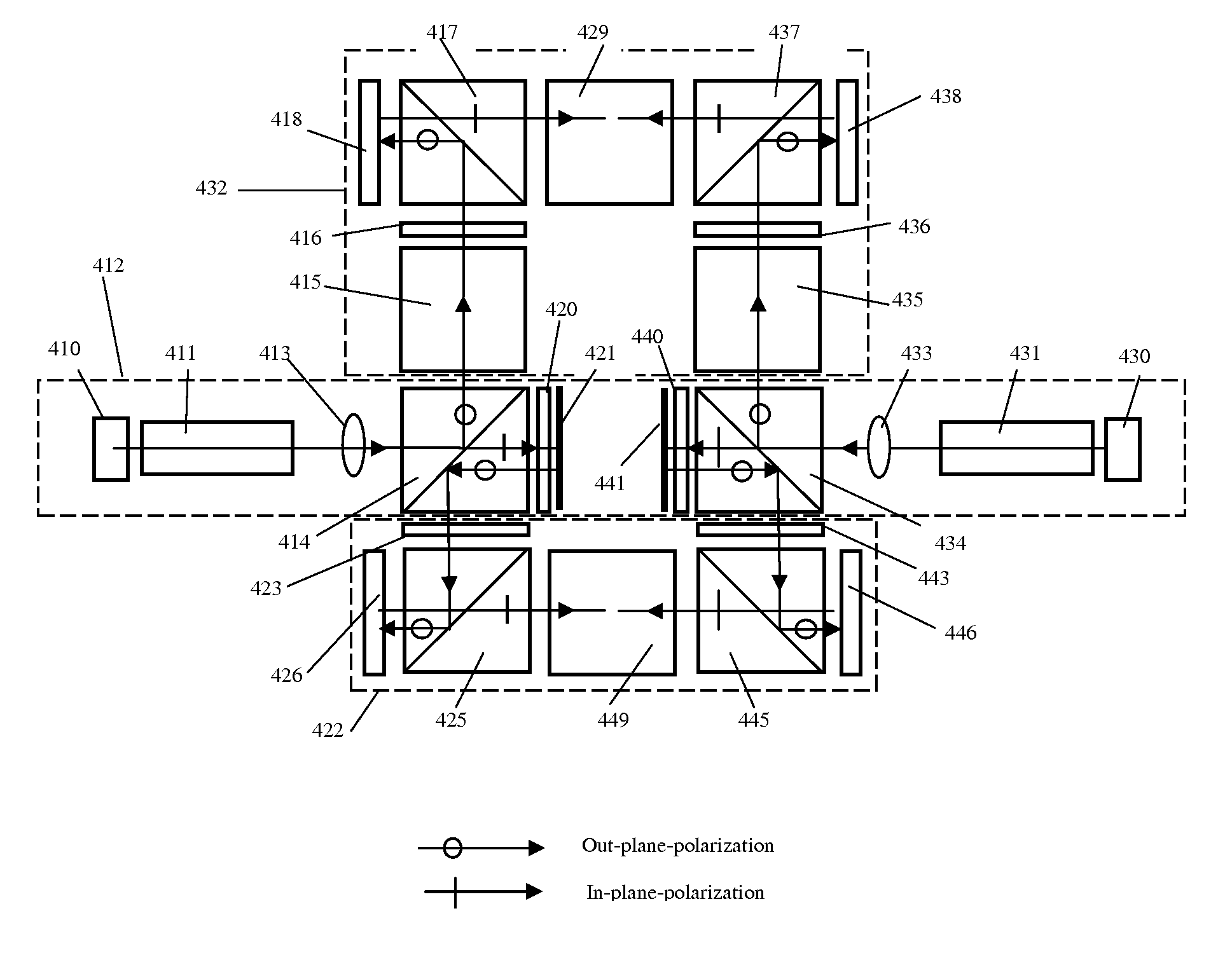
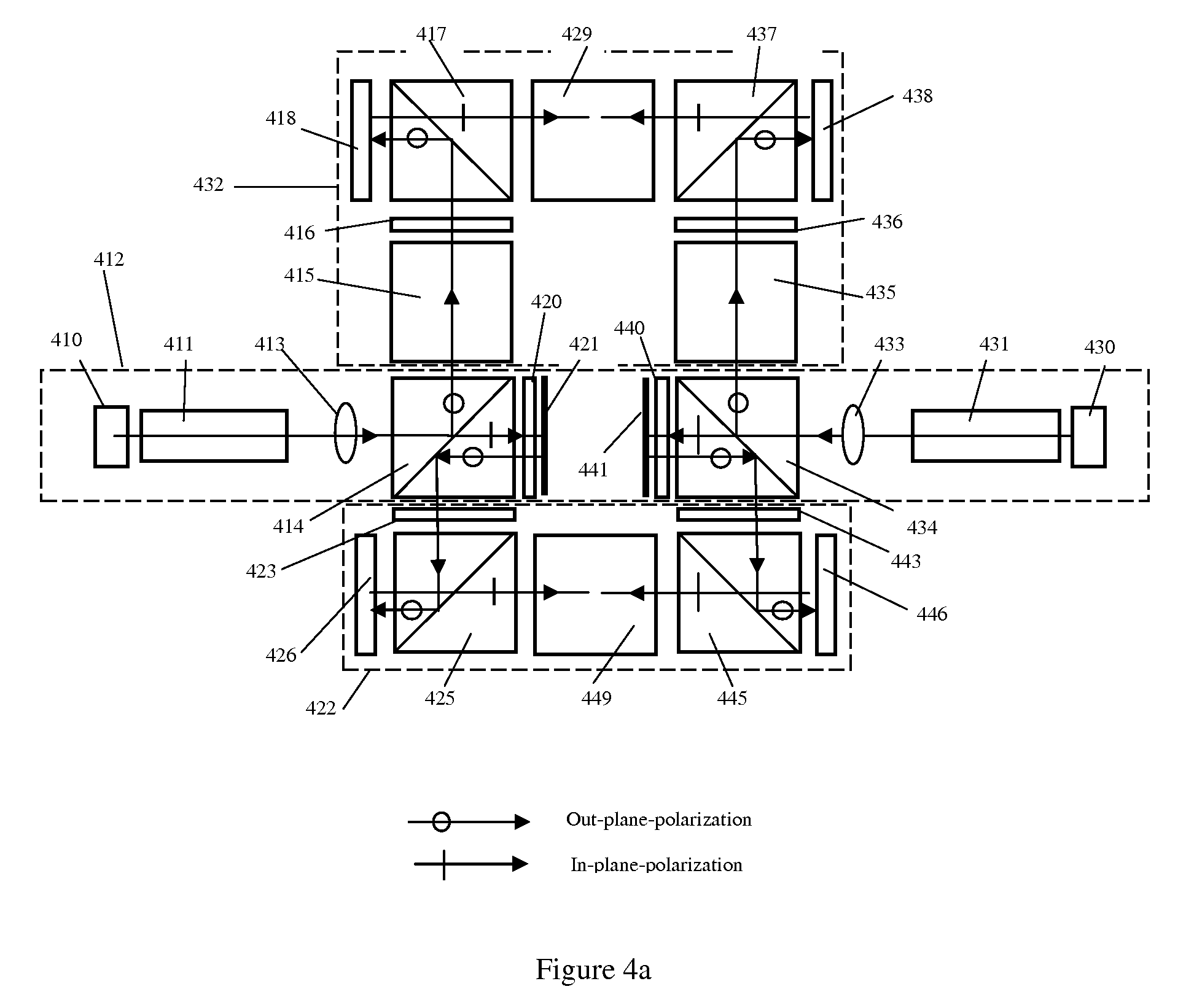
[0035]In this invention, a novel digital simultaneously stereoscopic image display is disclosed. The term “simultaneously stereoscopic image display” is referred to the display means in which the stereoscopic image pairs, which are recorded with synchronized shutters simultaneously, is displayed through two optical channels at same time, and viewed individually by left and right eye of the observer. In the present design, the optics of the stereoscopic display can use solid state light source efficiently and also enable the sharing of a number of optical components by both channels. As a result, the optical system is more compact, optically efficient and meanwhile less costly. In addition, the use of solid light sources not only increases the reliability and life time of the light source significantly, but also enlarges the color gamut of display. The solid state light sources discussed in this invention include, but not are limited to, light emitting diode (LED), super luminescent ...


PUM


Abstract

The present disclosure is a novel design of a polarization based stereoscopic display system that efficiently utilizes the optical energy from three primary color solid state light sources of random polarization, combines the three primary colors into a full color beam of a single polarization state to enable passive separation of the two image channels. The high optical energy efficiency is achieved by splitting each primary color light into two orthogonal polarization states. The single polarization state of the combined full color image beam is achieved by employing a spectrally selective light beam combiner or X-cube. By making the optical configuration of sub-module basically identical and sharing a number of optical components among color and image channels, the size and cost is reduced. By compensating the depolarization effect that is introduced by folding mirror(s), the cross talk between the two displayed stereo images is minimized.

Description

CROSS REFERENCE TO RELATED APPLICATIONS[0001]This application claims the benefit of provisional patent application Ser. No 60 / 995,463, filed Sep. 27, 2007 by the present inventors.[0002]US patent[0003]US2006 / 0007538[0004]US2006 / 0291053FIELD OF THE INVENTION[0005]The present invention relates to stereoscopic display and in particular, to the design of a stereoscopic display system employing solid state light sources.BACKGROUND OF THE INVENTION[0006]Traditionally, the stereoscopic image display systems are based on two forms of projection technology. i.e. sequential and simultaneous. In both approaches, two images are generated from two micro-display devices and are projected to a special screen, on which one image is made to be seen only by the left eye and the other image by the right eye. The difference between the images yields depth information, and therefore resulting in strong stereoscopic sensation when they are seen by an observer.[0007]In the sequential approach, the two dis...

Claims


Application Information

Patent Timeline
Patent Type & Authority Applications(United States)
IPC IPC(8): H04N13/04H04N13/363
CPCH04N13/0459H04N13/0434H04N13/337H04N13/363
Inventor SU, WEI
Owner SU WEI
Why Eureka
Try Eureka