Dual mode camera solution apparatus, system, and method

a technology of dual-mode cameras and camera solutions, applied in the field of digital cameras, can solve the problems of imposing other system tradeoffs, difficult to achieve good image quality, and comparatively high cost of cmos image sensors specialized to achieve high dynamic range. achieve the effect of high dynamic rang

Inactive Publication Date: 2009-04-02
OMNIVISION TECH INC
View PDF14 Cites 322 Cited by
  • Summary
  • Abstract
  • Description
  • Claims
  • Application Information

AI Technical Summary

Benefits of technology

[0005]A dual mode camera solution provides system control over the dynamic range. A first portion of the system includes an image sensor. A second portion of the system includes an image signal processor, a buffer, and a dynamic range mode controller. The dynamic range mode controller selects the operating mode of the camera system. One operating mode has a normal dynamic range that is less than a high dynamic range (a non-HDR operating mode). Another operating mode has a high dynamic range (HDR operating mode). System control permits the operating mode to be selected in various ways, depending on application requirements such as a static selection of one operating mode or a dynamic selection of operating mode based on environmental conditions. System control also permits different types of image sensors to be used in the system, including image sensors that natively support HDR and non-HDR operating modes as well as image sensors that natively support only a non-HDR operating mode.

Problems solved by technology

One problem caused by a narrow dynamic range is that it is difficult to achieve a good image quality when there is a high contrast between very bright and very dark objects mixed in a field.
While high dynamic range CMOS image sensors are known in the prior art, they typically impose other system tradeoffs.
Additionally, a CMOS image sensor that is specialized to achieve a high dynamic range may be comparatively expensive.
Moreover, prior art high dynamic range image sensor chips typically do not permit flexible control over dynamic range at the system level.

Method used


Image

  • Dual mode camera solution apparatus, system, and method
  • Dual mode camera solution apparatus, system, and method
  • Dual mode camera solution apparatus, system, and method

Examples


Embodiment Construction

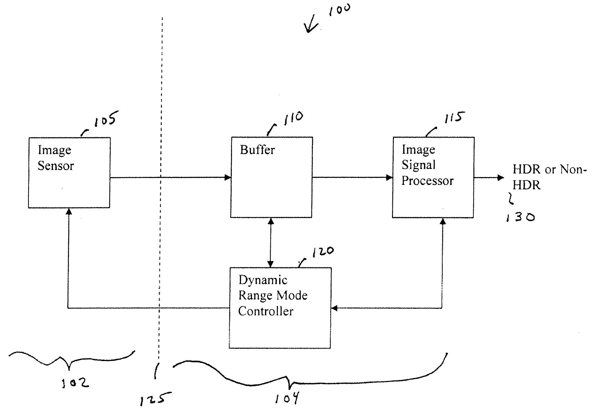
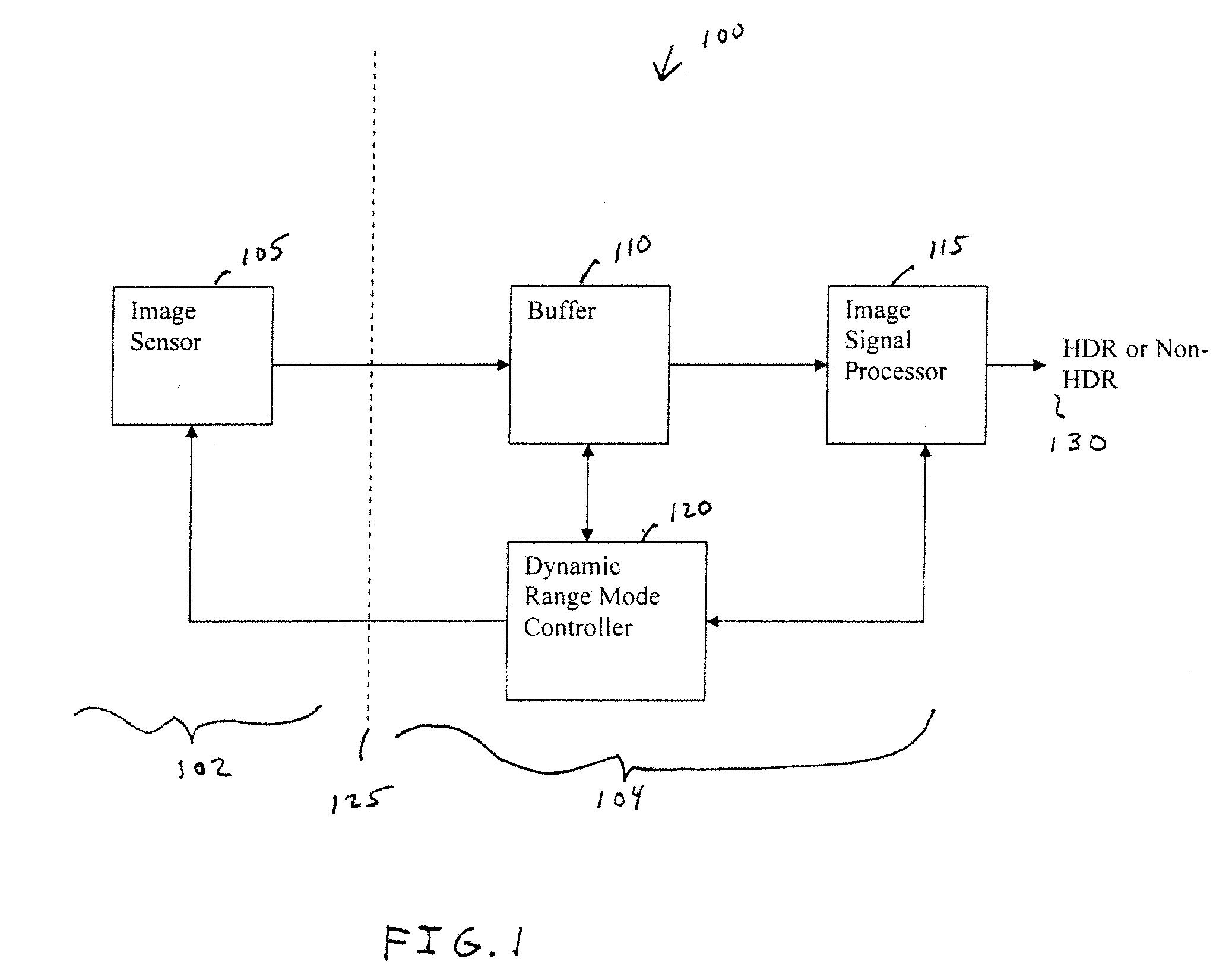
[0011]FIG. 1 is a block diagram illustrating a camera system 100 in accordance with one embodiment of the present invention with some conventional components omitted for clarity. The camera system 100 can be considered as having two portions. A first portion 102 includes an image sensor 105 having an array of pixels. In one embodiment image sensor 105 is a CMOS image sensor. Image sensor 105 generates image signals, where each image signal corresponds to raw (unprocessed) pixel data of an image.

[0012]A second portion 104 is an image processing and control portion of the system. Second portion 104 includes a buffer 110 to buffer image signals, image signal processor 115, and dynamic range mode controller 120. It will be understood that the function of the image signal processor 115 may be implemented using a digital signal processor or other suitable processor capable of processing image signals. As described below in more detail, dynamic range mode controller 120 is preferably desig...


PUM


Abstract

A camera solution includes an image sensor and an image processing and control system. At least two different operating modes are supported, with one of the modes having a higher dynamic range. Control of the dynamic range is provided at the system level. The system supports statically or dynamically selecting an operating mode that determines the dynamic range of a camera. In one implementation, the system supports the use of either a conventional image sensor that does not natively support a high dynamic range or a dual-mode image sensor.

Description

FIELD OF THE INVENTION[0001]The present invention is generally related to digital cameras having an image sensor with an array of pixels. More particularly, the present invention is directed to cameras having a high dynamic range.BACKGROUND OF THE INVENTION[0002]Conventional CMOS image sensors used in consumer products have a dynamic range that is typically limited to about 60-70 dB. One problem caused by a narrow dynamic range is that it is difficult to achieve a good image quality when there is a high contrast between very bright and very dark objects mixed in a field.[0003]There is increasing interest in using high dynamic range complementary metal oxide semiconductor (CMOS) image sensors in consumer applications, such as in automobile cameras. In many applications a high dynamic range of 90-100 dB is desired. While high dynamic range CMOS image sensors are known in the prior art, they typically impose other system tradeoffs. As one example, the attainment of a high dynamic range...

Claims


Application Information

Patent Timeline
Patent Type & Authority Applications(United States)
IPC IPC(8): H04N3/15
CPCH04N5/23245H04N5/2355H04N5/2353H04N23/667H04N23/741H04N23/73
Inventor LI, HONGJUNHE, JAMES XINPINGYANG, HENRY HONGLI
Owner OMNIVISION TECH INC
Why Eureka
Try Eureka