Liquid Crystal Display Device

a liquid crystal display and display device technology, applied in non-linear optics, instruments, optics, etc., can solve the problems of unhardened objects leaking from the frame, black-painted parts exfoliating, attached surfaces may exfoliate together with paint, etc., to achieve the effect of preventing exfoliation and without degrading design features

Active Publication Date: 2009-04-02
PANASONIC LIQUID CRYSTAL DISPLAY CO LTD +1
View PDF4 Cites 5 Cited by
  • Summary
  • Abstract
  • Description
  • Claims
  • Application Information

AI Technical Summary

Benefits of technology

[0020]The present invention makes it possible to provide a liquid crystal display device capa

Problems solved by technology

Meanwhile, when the housing and the protection plate of a liquid crystal television are combined, the back side of the protection plate will be fixed to the housing because fixing the liquid crystal panel to the housing may cause fluctuations of the gap distance of the liquid crystal layer.
Therefore, if the protection plate is attached to the painted surface, the attached surface may exfoliate together with the paint due to the weight.
Even if a certain coupler is provi

Method used


Image

  • Liquid Crystal Display Device
  • Liquid Crystal Display Device
  • Liquid Crystal Display Device

Examples


first embodiment

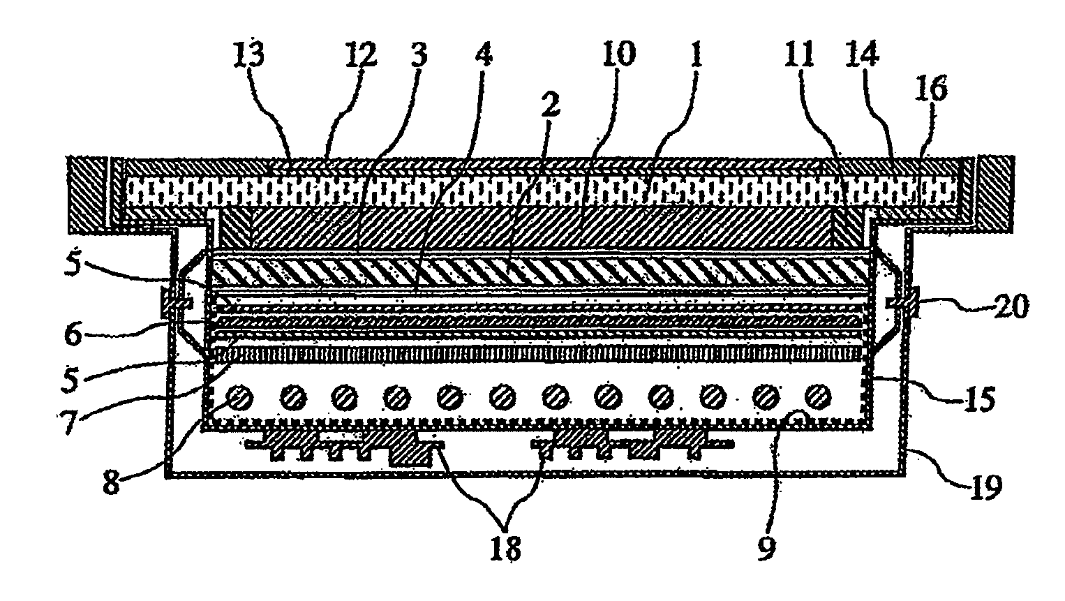
[0047]A first embodiment will be explained below with reference to FIG. 1. With a liquid crystal display device according to the present invention, the black coloring layer 14 is formed at the ends of four sides on the surface of the protection plate 1 so that the adhesion layer 16 and the frame 11 can be hidden, enabling only an image to be displayed on the surface of the protection plate. The present embodiment allows the black coloring layer 14 and the anti-glare film to be disposed in the same plane without level difference on the surface.

[0048]Further, an anti-glare layer 12 is formed above the protection plate 1 to restrain reflection of surrounding scenery to the protection plate 1, thereby improving the visibility. With the present embodiment, the anti-glare layer 12 is formed above the protection plate 1 through the adhesion layer 13. To attain the thick black coloring layer 14 while reflection of surrounding scenery to the display region is restrained, the anti-glare film ...

second embodiment

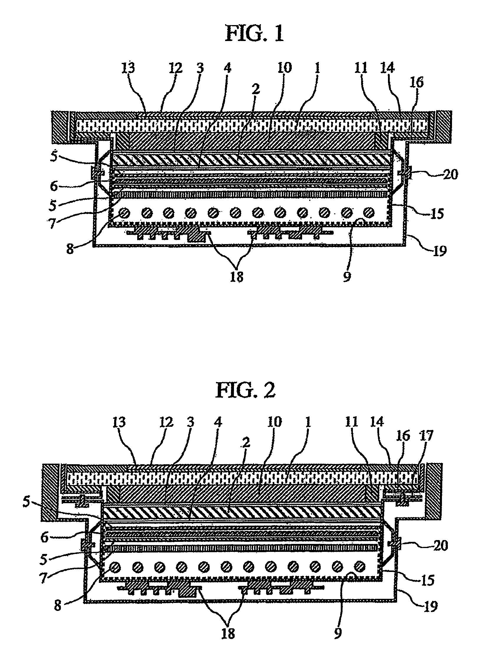
[0051]A second embodiment will be explained below with reference to FIG. 3.

[0052]Like the first embodiment, the black coloring layer 14 is formed on the protection plate 1 so that the adhesion layer 16 and the frame 11 can be hidden, thereby making it possible to display only an image on the surface of the protection plate 1.

[0053]Further, the anti-glare film (the adhesion layer 13 and the anti-glare layer 12) is formed above the surface of the protection plate 1 including the black coloring layer 14. That is, the anti-glare layer and the adhesion layer are formed above the black coloring layer and the protection plate. The effects obtained by such a constitution are that joint seams on the surface of the protection plate 1 are eliminated, making it easier to wipe off dust on the anti-glare layer 12 using a dustcloth dampened with water or the like. Further, since the anti-glare film is provided on the black coloring layer 14, an effect of preventing exfoliation of the black colorin...

third embodiment

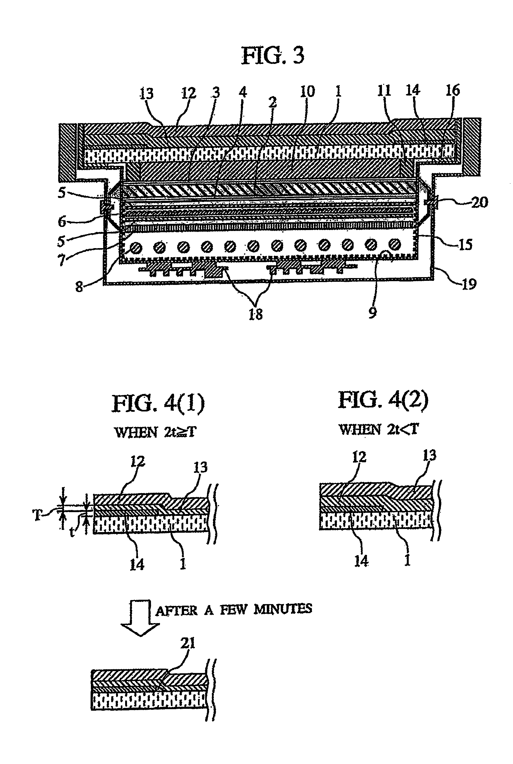
[0055]A third embodiment will be explained below with reference to FIG. 4.

[0056]If the adhesion layer 13 of the anti-glare film is thin, air bubbles 21 may be generated in the vicinity of the end of the black coloring layer 14 when a certain period of time has elapsed after the anti-glare film is attached to the protection plate 1. Since these air bubbles are generated in the image display region, there arises a problem of degraded visibility of image, as shown in FIG. 4(1).

[0057]As a result of our study, it turns out that the thinner the adhesion layer 13 of the anti-glare film and the thicker the black coloring layer, the easier becomes air bubbles 21 to be generated. Further, when T denotes the thickness of the adhesion layer 13 of the anti-glare film; and t, the thickness of the black coloring layer, it turns out that the generation of air bubbles 21 can be restrained when a relation 2t4(2), which satisfies a relation 2t21 in the vicinity of the end of the black coloring layer 1...


PUM


Abstract

An object of the present invention is to propose the structure and constitution of a liquid crystal display device having a protection plate, which prevents exfoliation of black painting at ends of the protection plate when dust on the protection plate of the liquid crystal display device is wiped off, thus preventing degradation of design features.
The liquid crystal display device comprises: a transparent protection plate formed above a liquid crystal panel; a pair of polarizing plates disposed to sandwich and hold the liquid crystal panel; a transparent organic medium layer formed between the protection plate and the liquid crystal panel; a black coloring layer formed at ends of four sides on a side of the protection plate, the side being opposite to a side at which the transparent organic medium layer is disposed; and an anti-glare film composed of an anti-glare layer and an adhesion layer formed on a side of the protection plate, the side being opposite to a side at which the transparent organic medium layer is disposed.

Description

BACKGROUND OF THE INVENTION[0001]1. Field of the Invention[0002]The present invention relates to a liquid crystal display device which includes a liquid crystal layer between a pair of substrates.[0003]2. Description of the Related Art[0004]With a liquid crystal display device using liquid crystal, light from light sources passes through a liquid crystal layer, a color filter, a polarizing plate, etc. before an image is recognized. In this case, a polarizing plate is provided at the outermost surface of a liquid crystal display device for a personal computer monitor or a liquid crystal television. To restrain surface reflection, an anti-glare (AG) film having fine irregularities or an antireflection film is provided on the surface of the polarizing plate. There is a liquid crystal panel made of a glass plate having a thickness of about 0.5 to 0.7 mm under the polarizing plate.[0005]The glass plate under the polarizing plate for such a personal computer monitor and a liquid crystal t...

Claims


Application Information

Patent Timeline
IPC IPC(8): G02F1/1335G02F1/1333
CPCG02F1/133308G02F2201/503G02F2001/133311G02F1/133502G02F1/133311G02F1/1333G02F1/1335
Inventor SASAKI, HIROSHISUGIBAYASHI, MAKIKOTOMIOKA, YASUSHIKONDO, KATSUMI
Owner PANASONIC LIQUID CRYSTAL DISPLAY CO LTD
Why Eureka
Try Eureka