Liquid crystal display panel and array substrate thereof

a technology of liquid crystal display and array substrate, which is applied in non-linear optics, instruments, optics, etc., can solve the problems of color shift or color washout phenomenon, display luminance of display products in other directions may be degraded, and achieve the effect of effective compensation effect, good display quality, and same maximum display luminan

Active Publication Date: 2009-04-02
AU OPTRONICS CORP
View PDF9 Cites 15 Cited by
  • Summary
  • Abstract
  • Description
  • Claims
  • Application Information

AI Technical Summary

Benefits of technology

[0018]The present invention adopts a design of alignment patterns with different extending directions in the LCD panel so as to produce a more effective compensation effect to the display effect of the LCD panel in a specific direction to further satisfy the demand of users on a larger range of viewing angles in the above-mentioned specific direction. Besides, the LCD panel of the present invention still has the almost same maximum display luminance as that of a conventional LCD panel. In this way, the LCD panel of the present invention not only has an extraordinary wide range of viewing angles in a specific direction, but also keeps good display quality as viewing at a smaller viewing angle or as front viewing.

Problems solved by technology

However, restricted by the optical behavior of the liquid crystal molecules themselves, when an MVA LCD panel is viewed by a user in different viewing directions, a color shift or color washout phenomenon may occur.
Though such a design scheme is able to widen the range of viewing angles in the specific directions, the display luminance of a display product in other directions may be degraded.

Method used


Image

  • Liquid crystal display panel and array substrate thereof
  • Liquid crystal display panel and array substrate thereof
  • Liquid crystal display panel and array substrate thereof

Examples


Embodiment Construction

[0027]Reference will now be made in detail to the present preferred embodiments of the invention, examples of which are illustrated in the accompanying drawings. Wherever possible, the same reference numbers are used in the drawings and the description to refer to the same or like parts.

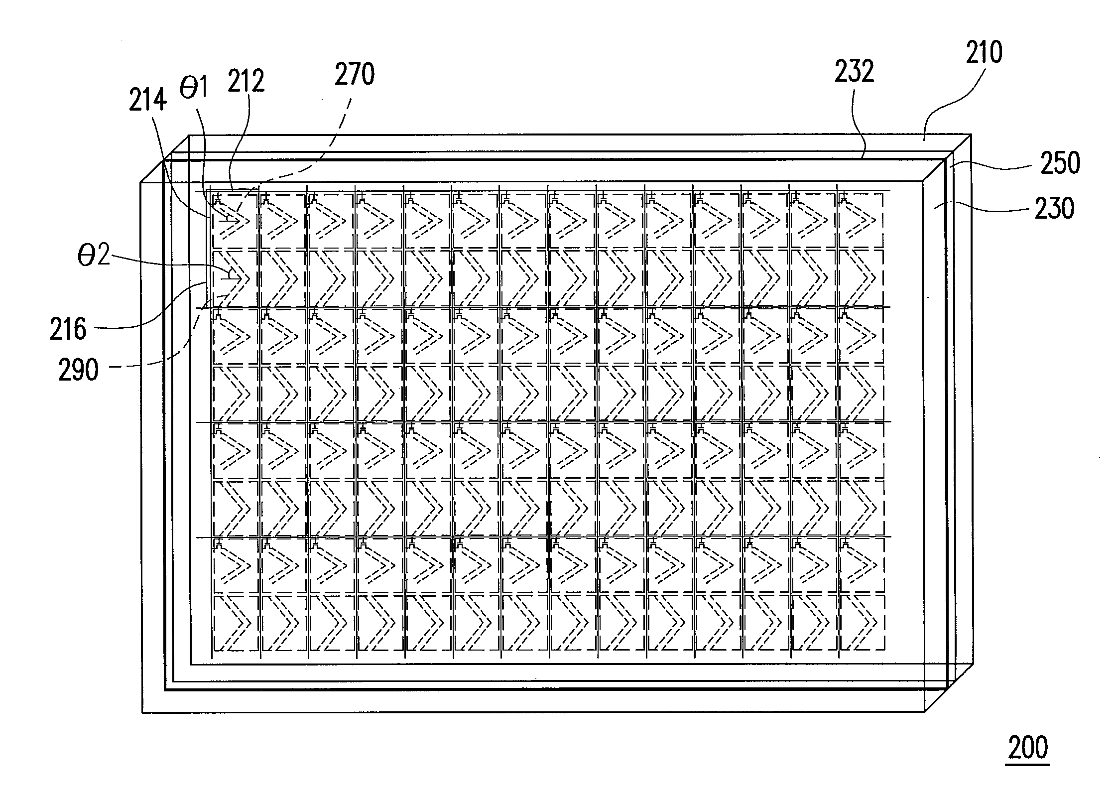
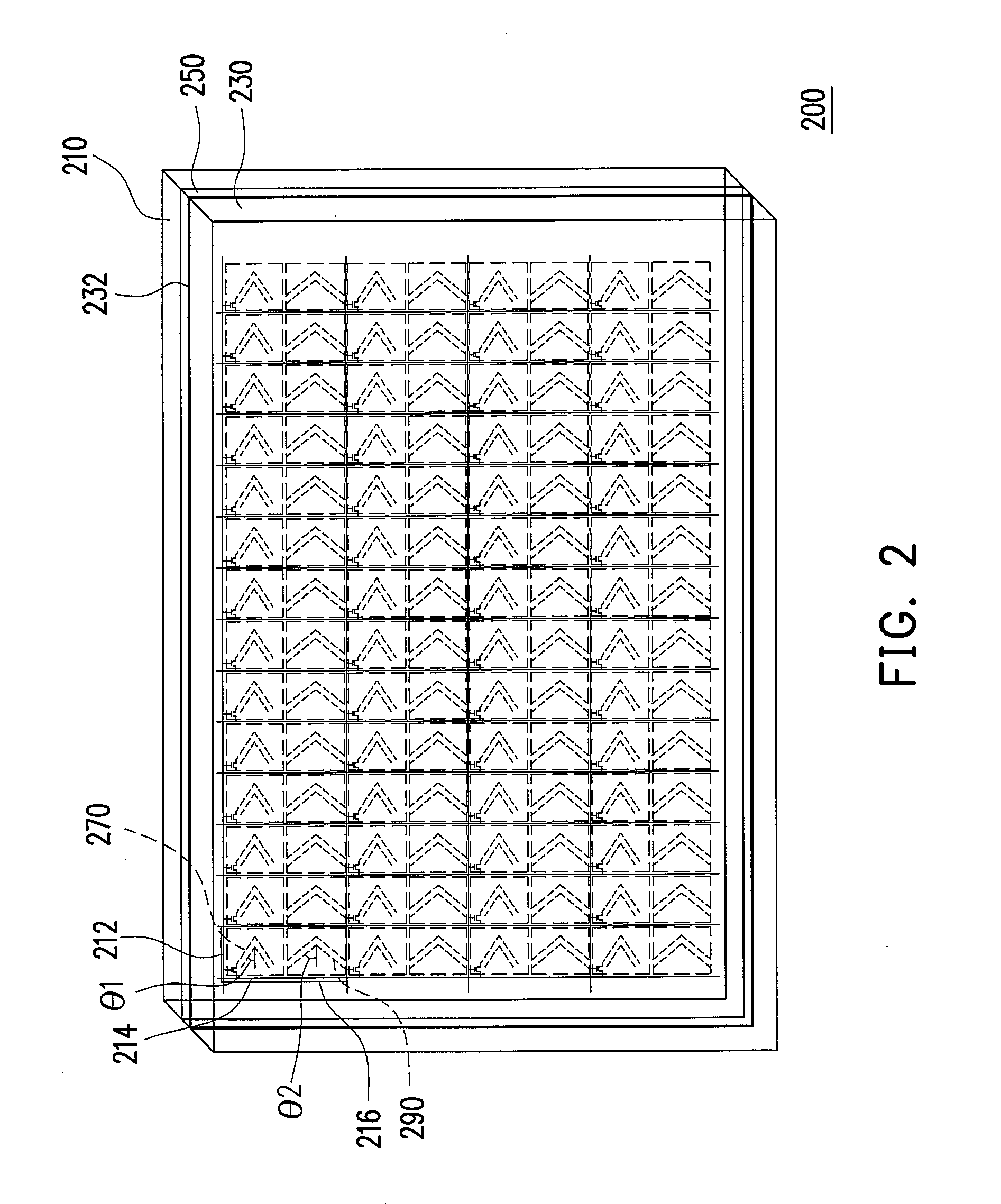
[0028]FIG. 2 is a schematic perspective drawing of an LCD panel according to an embodiment of the present invention. Referring to FIG. 2, an LCD panel 200 includes an array substrate 210, an opposite substrate 230, a liquid crystal layer 250, a plurality of first alignment patterns 270 and a plurality of second alignment patterns 290. The array substrate 210 includes a plurality of scan lines 212, a plurality of data lines 214 and a plurality of pixel units 216. The scan lines 212 and the data lines 214 are respectively electrically connected to a corresponding pixel unit 216. The opposite substrate 230 includes opposite electrodes 232, and the liquid crystal layer 250 is disposed between the array s...


PUM

PropertyMeasurementUnit
acute angleaaaaaaaaaa
included angleaaaaaaaaaa

Abstract

A liquid crystal display panel includes an array substrate, an opposite substrate having an opposite electrode, a liquid crystal layer located therebetween, first alignment patterns and second alignment patterns. The array substrate includes scan lines, data lines and pixel units electrically connecting corresponding scan lines and data lines. Each pixel unit includes a first active device, a first pixel electrode electrically connecting the first active device and a second pixel electrode. The first pixel electrode and the second pixel electrode are separated to define a first displaying region and a second displaying region. The extending directions of the first alignment patterns in the first displaying region and the second alignment patterns in the second displaying region respectively intersect the extending direction of the scan lines at a smaller first acute angle and a greater acute angle for controlling the arrangements of the liquid crystal molecules.

Description

CROSS-REFERENCE TO RELATED APPLICATION[0001]This application claims the priority benefit of Taiwan application serial no. 96135918, filed on Sep. 27, 2007. The entirety of the above-mentioned patent application is hereby incorporated by reference herein and made a part of this specification.BACKGROUND OF THE INVENTION[0002]1. Field of the Invention[0003]The present invention generally relates to a liquid crystal display (LCD) panel and an array substrate thereof, and more particularly, to an LCD panel with wide viewing feature.[0004]2. Description of Related Art[0005]As the LCD technology continuously advances towards a bigger display screen, in order to overcome the limited viewing angle problems with a big screen specification, the related LCD manufactures continuously strive to develop the wide viewing techniques so as to expect a breaking though, wherein a significant result, multi-domain vertical alignment LCD panel (MVA LCD panel), belongs to one of familiar wide viewing techn...

Claims


Application Information

Patent Timeline
Patent Type & Authority Applications(United States)
IPC IPC(8): G02F1/1337G02F1/1343
CPCG02F1/133753G02F1/133707
Inventor CHEN, CHIEH-WEITSAO, CHENG-HANCHAN, TE-WEISU, JENN-JIA
Owner AU OPTRONICS CORP
Why Eureka
Try Eureka