Light guide plate, light guide plate unit, and planar lighting device

a planar lighting and light guide plate technology, applied in lighting device details, lighting and heating apparatuses, instruments, etc., can solve the problems of uneven brightness on the light exit plane, lower light use efficiency of backlight units, and decrease in thickness, so as to minimize brightness unevenness and high light use efficiency , the effect of high light use efficiency

Inactive Publication Date: 2009-04-02
FUJIFILM CORP
View PDF11 Cites 37 Cited by
  • Summary
  • Abstract
  • Description
  • Claims
  • Application Information

AI Technical Summary

Benefits of technology

[0034]The first to sixth aspects of the invention produce effects that make it possible to provide a light guide plate and a light guide plate unit that has a thin configuration, yield a high light use efficiency, emits light with minimized unevenness in brightness, and achieve a brightness distribution representing a high-in-the-middle curve or a bell curve, whereby an area close to the center of the screen is brighter than the periphery thereof as required of thin, large-screen liquid crysta...

Problems solved by technology

While a thin design may be achieved with backlight units such as the tandem type, of which the thickness decreases with the increasing distance from the light source, those backlight units yielded lower light use efficiency than the direct illumination type because of the relative dimensions of the cold cathode tube to the reflector.
Further, where the light guide plate used is shaped to have grooves for receiving cold cathode tubes, although such a light guide plate could be shaped to have a thickness that decreases with the increasing distance from the cold cathode tube, if the light guide plate is made thinner, brightness at locations immediately above the cold cathode tube disposed in the grooves increased, thus causing uneven brightness on the light exit plane to stand out.
In addition, all thes...

Method used


Image

  • Light guide plate, light guide plate unit, and planar lighting device
  • Light guide plate, light guide plate unit, and planar lighting device
  • Light guide plate, light guide plate unit, and planar lighting device

Examples


example 1

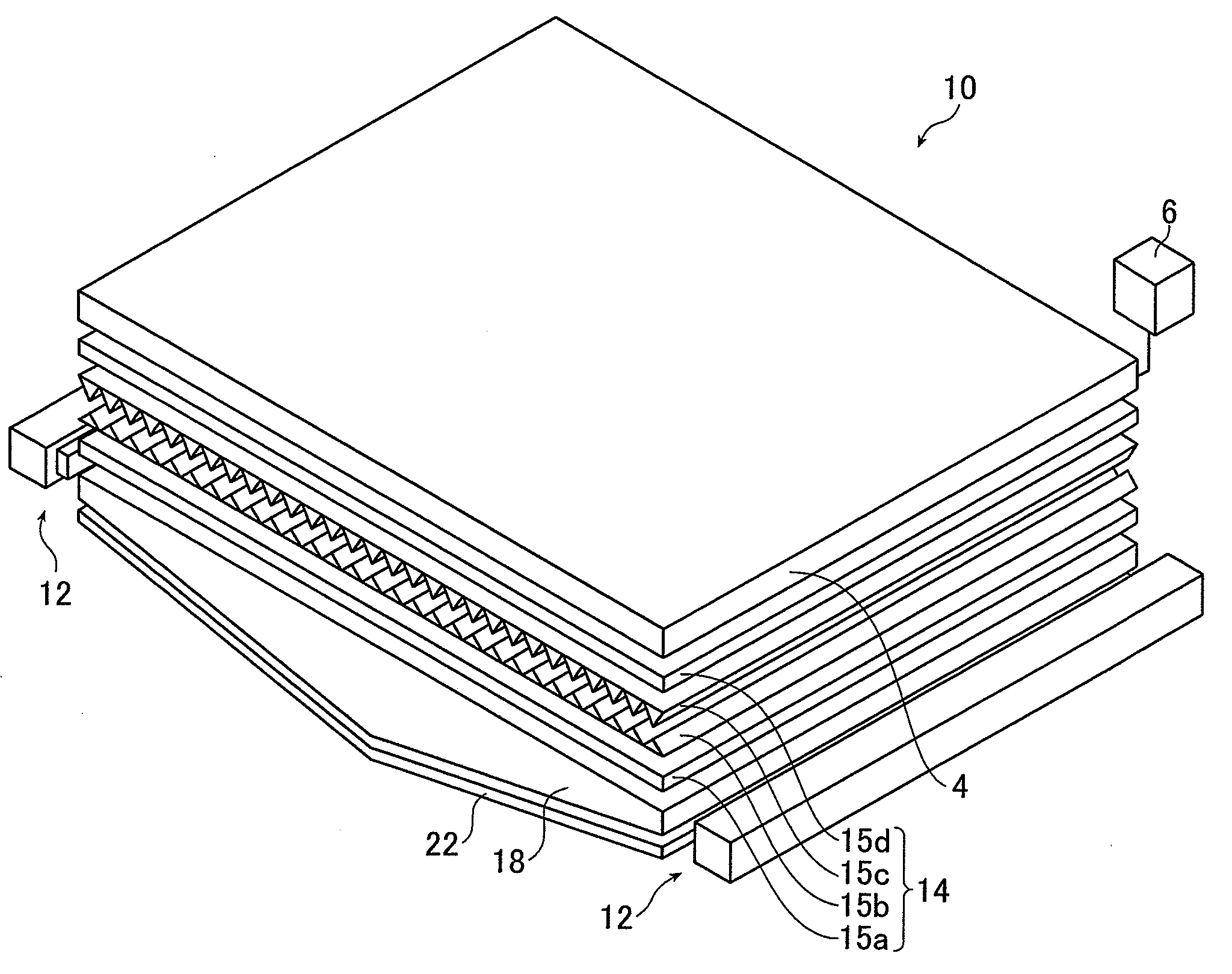
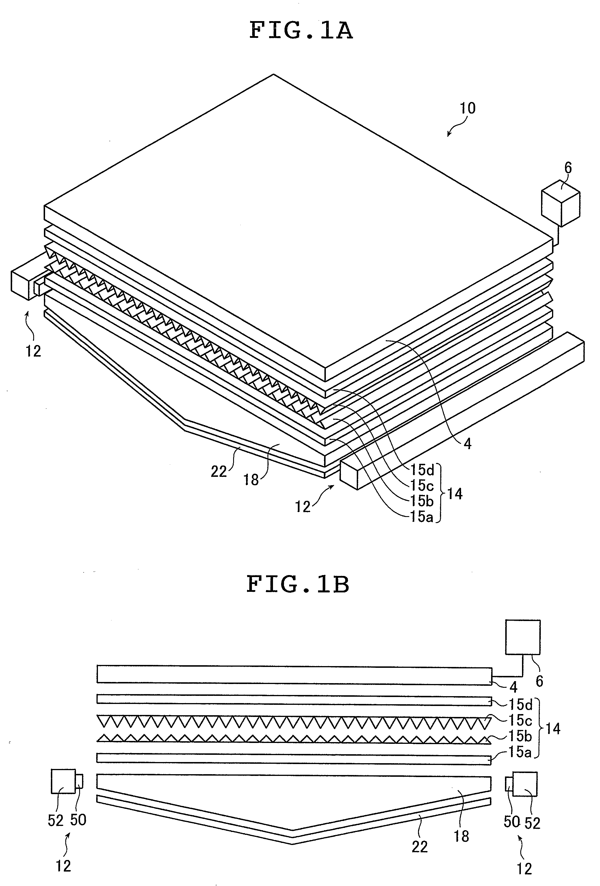
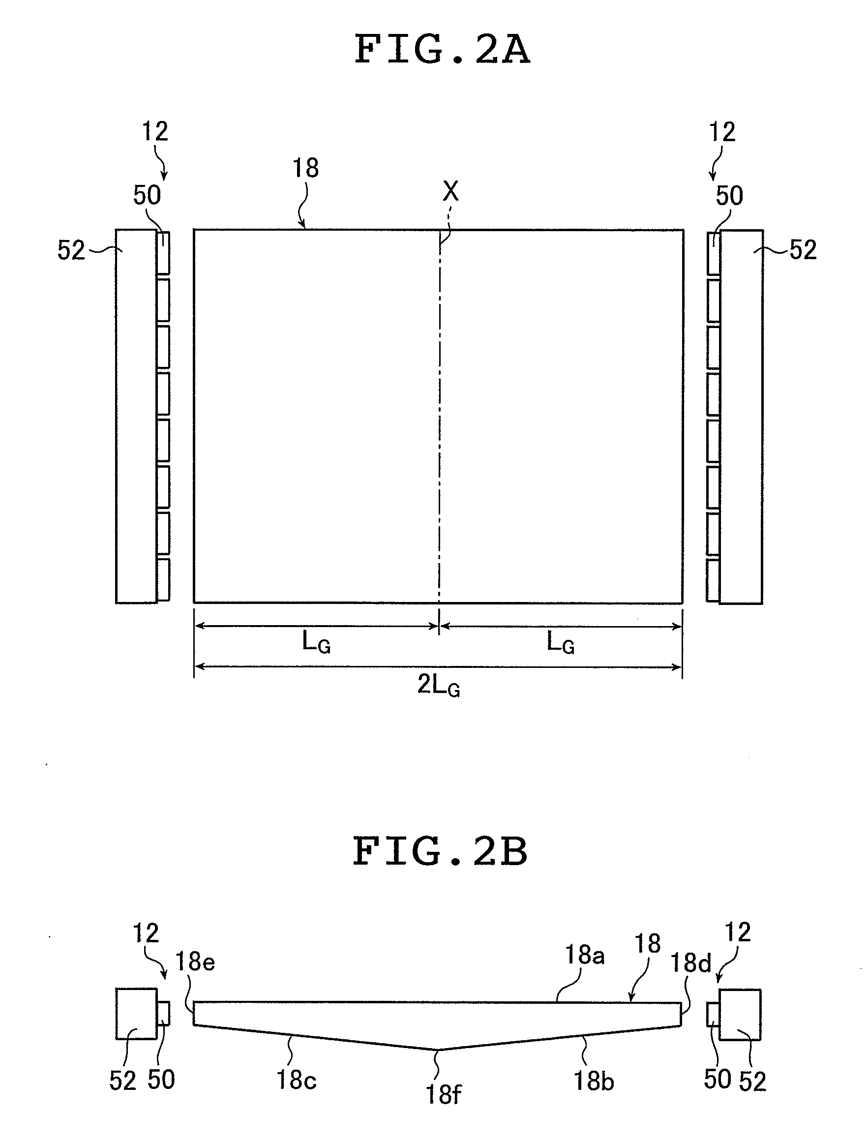
[0209]In Example 1, a light guide plate 18 having a light guiding length L of 480 mm for a screen size of 37 inches was used to obtain the taper [degree], the radius of curvature R of the central portion (curved portion) [mm], the light use efficiency [%], and the middle-high ratio [%] by varying the maximum thickness [mm], the minimum thickness [mm], the particle diameter [μm], and the particle density [wt %] as shown in Tables 2 and 3. Tables 2 and 3 show the results.

[0210]Table 2 shows examples 11 to 16 according to the invention related to Example 1; Table 3 shows Comparative Examples 11 to 16 related to Example 1.

TABLE 2Example 1Examples according to the invention111213141516Screen size37″37″37″37″37″37″Light guiding480480480480480480length [mm]Maximum3.481.493.513.483.483.48thickness[mm]Minimum20.51222thickness[mm]Particle7774.5912diameter [μm]Particle0.0650.0490.0970.0470.0840.122density[wt %]Taper [deg.]0.4770.3580.7160.4770.4770.477Central15000270007000150001500015000portio...

example 2

[0217]In Example 2, light guide plates 18 having light guiding lengths L of 560 mm and 590 mm for screen sizes of 42 inches and 46 inches, respectively, were used to obtain the taper [degree], the radius of curvature R of the central portion (curved portion), the light use efficiency [%], and the middle-high ratio [%] by varying the maximum thickness [mm], the minimum thickness [mm], the particle diameter [μm], and the particle density [wt %] as shown in Tables 4 and 5. Tables 4 and 5 show the results.

[0218]Table 4 shows examples 21 to 24 according to the invention related to Example 2; Table 5 shows Comparative Examples 21 to 23 related to Example 2.

TABLE 4Example 2Examples according to the invention21222324Screen size42″46″42″46″Light guiding560590560590length [mm]Maximum thickness3.483.483.483.5[mm]Minimum thickness2221.5[mm]Particle diameter77127[μm]Particle density0.0480.0430.090.054[wt %]Taper [deg.]0.4110.390.4110.486Central portion R20000220002000015000[mm]Light use61616159e...

example 3

[0222]In Example 3, light guide plates 18 having light guiding lengths L of 660 mm and 730 mm for screen sizes of 52 inches and inches, respectively, were used to obtain the taper [degree], the radius of curvature R of the central portion (curved portion), the light use efficiency [%], and the middle-high ratio [%] by varying the maximum thickness [mm], the minimum thickness [mm], the particle diameter [μm], and the particle density [wt %] as shown in Tables 6 and 7. Tables 6 and 7 show the results.

[0223]Table 6 shows examples 31 and 32 according to the invention related to Example 3; Table 7 shows Comparative Examples 31 to 35 related to Example 3.

TABLE 6Example 3Example according tothe invention3132Screen size52″57″Light guiding length660730[mm]Maximum thickness3.53.48[mm]Minimum thickness22[mm]Particle diameter77[μm]Particle density0.0350.028[wt %]Taper [deg.]0.3510.317Central portion R2800033000[mm]Light use efficiency6061[%]Middle-high ratio [%]1414.2

TABLE 7Comparative ExampleC...


PUM


Abstract

The light guide plate includes a light exit plane, two light entrance planes, two symmetrical inclined rear planes increasingly distanced from the light exit plane from the two light entrance planes toward a center of the light exit plane, a curved portion joining the two inclined rear planes and scattering particles for scattering light travelling inside the light guide plate. The light guide plate satisfies given ranges set for a length between the two light entrance planes, a thickness of each of the two light entrance planes, a thickness at the center of the curved portion, a radius of curvature thereof, tapers of the inclined rear planes, and a particle diameter and a density of the scattering particles, and conditions that a light use efficiency be 55% or greater and that a middle-high ratio represented by the brightness distribution at the light exit plane be greater than 0% and not greater than 25%.

Description

[0001]The entire contents of literature cited in this specification are incorporated herein by reference.BACKGROUND OF THE INVENTION[0002]The present invention relates to a light guide plate used in liquid crystal display devices and the like, a light guide plate unit using the light guide plate, and a planar lighting device using the light guide plate and the light guide plate unit.[0003]Liquid crystal display devices use a backlight unit for radiating light from behind the liquid crystal display panel to illuminate the liquid crystal display panel. A backlight unit is configured using a light guide plate for diffusing light emitted by an illuminating light source to irradiate the liquid crystal display panel and optical parts such as a prism sheet and a diffusion sheet for rendering the light emitted from the light guide plate uniform.[0004]Currently, large liquid crystal televisions predominantly use a so-called direct illumination type backlight unit comprising a light guide pla...

Claims


Application Information

Patent Timeline
IPC IPC(8): F21V7/04
CPCG02B6/0041G02B6/0056G02B6/0053G02B6/0051
Inventor OKUMURA, TAKAMITSU
Owner FUJIFILM CORP
Why Eureka
Try Eureka