Light guide plate for surface light source

Active Publication Date: 2009-04-02
STANLEY ELECTRIC CO LTD
View PDF5 Cites 82 Cited by
  • Summary
  • Abstract
  • Description
  • Claims
  • Application Information

AI Technical Summary

Benefits of technology

[0033]This causes the light guided from the light incident surface to the light guide plate to be scattered by the dots immediately after the light is guided. Therefore, it is possible to cause the light from a light source to be scattered in various places of the light guide plate immediately after the light from the light source is guided into the light guide plate, for example, in the case of using a point light source such as an LED as the light source of the light guided into the light guide p

Problems solved by technology

In this situation, it is very difficult to form a plurality of concave or convex portions corresponding to the dots on the formation surface by cutting or the like by using the stamper for use in forming the dot formation surface on the light guide plate.
Accordingly it is difficult to form a plurality of dots each having a desired shape on the dot formation surface of the light guide plate with accuracy.
Particularly, it is extremely difficult to adjust the angle of inclination of the side wall surface of each dot to an appropriate angle of inclination for each portion of the side wall surface with accuracy.
In addition, an edge of the side wall surface of a dot will be rounded in general, which easily causes light scattering in the portion.
Therefore, it is impossible to largely increase the dot density and thus impossible to sufficiently increase the proportion of the dot side wall surfaces useful for controlling the light distribution of the emitted light on the dot formation surface of the light guide plate.
Thereby, it has been diffic

Method used


Image

  • Light guide plate for surface light source
  • Light guide plate for surface light source
  • Light guide plate for surface light source

Examples


first embodiment

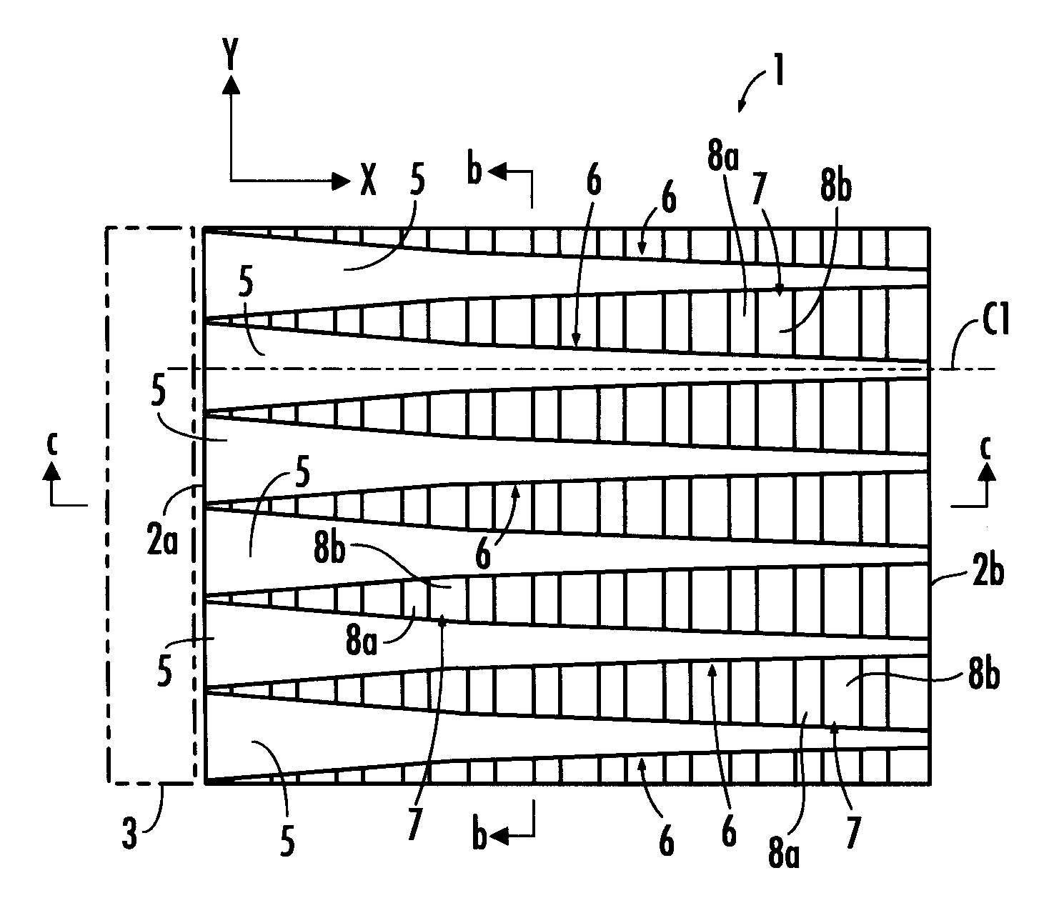
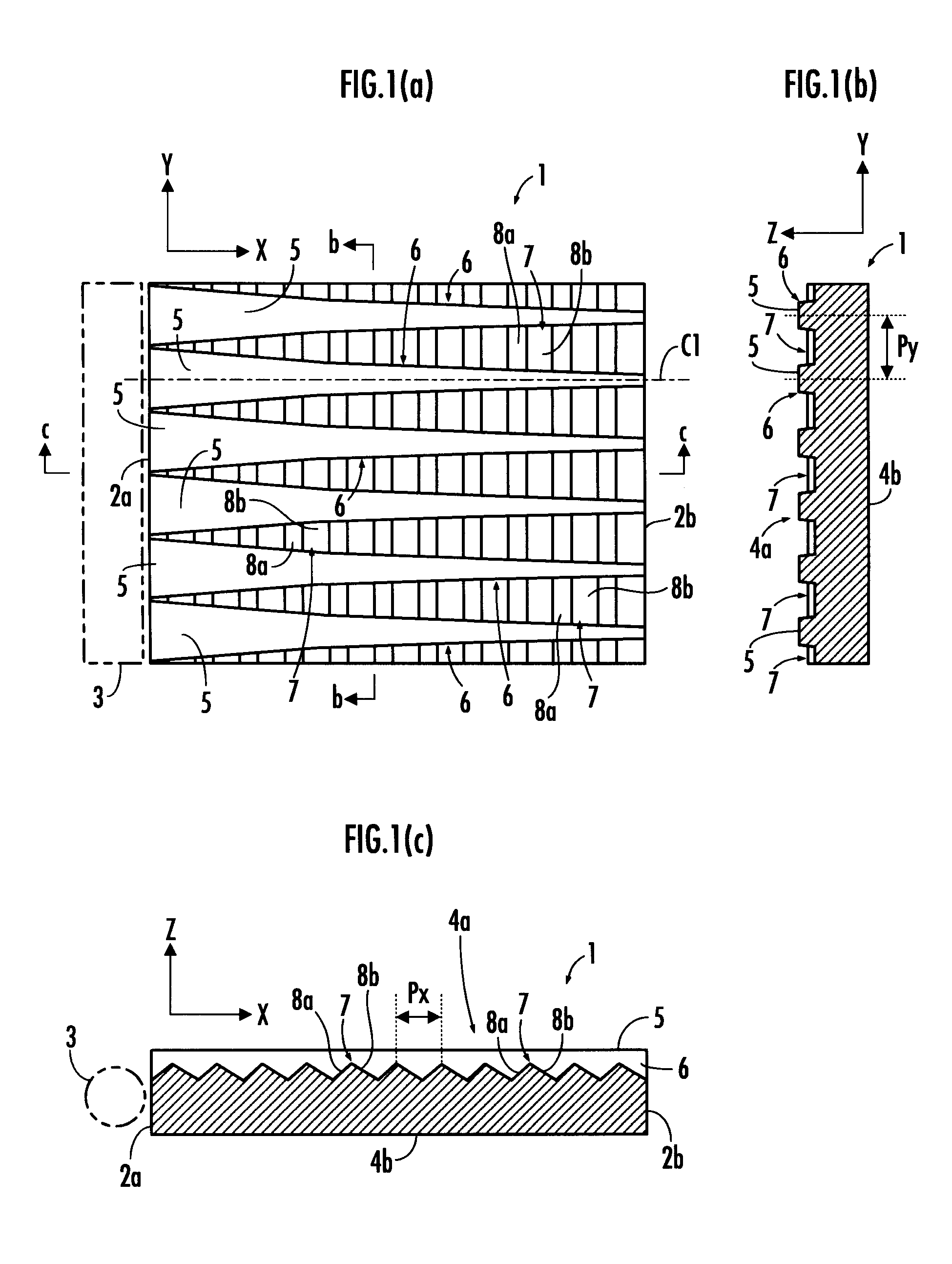
[0049]A first embodiment of the present invention will now be described with reference to FIG. 1 to FIG. 5. First, the structure of a light guide plate for a surface light source according to this embodiment will be described with reference to FIG. 1. FIG. 1A is a plan view of the light guide plate for a surface light source according to this embodiment, FIG. 1B is a sectional view taken along line b-b of FIG. 1A, and FIG. 1C is a sectional view taken along line c-c of FIG. 1A.

[0050]Referring to FIG. 1, a light guide plate for a surface light source 1 (hereinafter, simply referred to as “light guide plate 1”) according to this embodiment has a square plate-like appearance shape and is formed by a light-transmitting material such as acrylic resin or polycarbonate resin. One side surface 2a of a pair of side surfaces 2a and 2b, which are opposite to each other, of the light guide plate 1 is a light incident surface (an incident surface of light source light) from a light source 3 to t...

second embodiment

[0088]Subsequently, a second embodiment of the present invention will be described with reference to FIG. 6. FIG. 6A shows a plan view of a light guide plate for a surface light source 21 of this embodiment, viewed in the thickness direction (Z-axis direction) thereof, and FIG. 6B shows a diagram illustrating an expanded sectional view taken along line b-b of FIG. 6A. The light guide plate for a surface light source 21 (hereinafter, simply referred to as “light guide plate 21”) of this embodiment differs from the light guide plate 1 of the first embodiment only in a part of the configuration, and therefore the description will be made focusing on the differences. Furthermore, detailed descriptions will be omitted here, regarding the same components as those of the light guide plate 1 of the first embodiment.

[0089]The appearance shape and material of the light guide plate 21 of this embodiment are the same as the light guide plate of the first embodiment. In the light guide plate 21 ...

third embodiment

[0101]Subsequently, a third embodiment of the present invention will be described with reference to FIG. 7. FIG. 7 shows a plan view of a light guide plate for a surface light source 31 according to this embodiment, viewed in the thickness direction (Z-axis direction) thereof. The light guide plate for a surface light source 31 (hereinafter, simply referred to as “light guide plate 31”) of this embodiment differs from the light guide plate 1 of the first embodiment only in a part of the configuration, and therefore the description will be made focusing on the differences. Detailed descriptions will be omitted here, regarding the same components as those of the light guide plate 1 of the first embodiment.

[0102]Referring to FIG. 7, the light guide plate 31 of this embodiment differs from the light guide plate 1 of the first embodiment only in the formation patterns of flat surfaces 35a, 35b, and 35c in the light distribution control surface 4a, and other areas are the same as in the l...


PUM


Abstract

A plurality of mirror surfaces (5), which extend in a direction (X-axis direction) perpendicular to a light incident surface (2a), are formed side by side in a longitudinal direction (Y-axis direction) of the light incident surface (2a) on a light distribution control surface (4a) of both surfaces (4a, 4b) of a light guide plate (1) in a thickness direction (Z-axis direction) thereof, and a plurality of prisms (7) extending in the Y-axis direction are formed side by side in the X-axis direction in areas other than the mirror surfaces (5). The mirror surfaces 5 are formed in such a way that Y-axis direction widths thereof vary in the X-axis direction. This enables the setting of the light distribution characteristics and luminance distribution of emitted light, which are viewed in two directions, namely a longitudinal direction of the light incident surface of the light guide plate and the direction perpendicular to the light incident surface, to target light distribution characteristics and luminance distribution.

Description

BACKGROUND OF THE INVENTION[0001]1. Field of the Invention[0002]The present invention relates to a light guide plate for a surface light source, which is used as a backlight or the like of a liquid crystal display.[0003]2. Description of the Related Art[0004]As a light guide plate for a surface light source used as a backlight of a liquid crystal display, for example, there is already known one disclosed in Japanese Patent Application Laid-Open No. 2001-35224 (hereinafter, referred to as “Patent Document 1”) or Japanese Patent Application Laid-Open No. 2006-49286 (hereinafter, referred to as “Patent Document 2”). The light guide plate in Patent Document 1 has an incident surface of light source light, which is one side surface of the light guide plate, and one of both surfaces (the front surface and rear surface) in the thickness direction of the light guide plate is a reflective surface (a surface on which a reflective sheet is polymerized) for reflecting light guided into the ligh...

Claims


Application Information

Patent Timeline
IPC IPC(8): G02B6/00
CPCG02B6/0036G02B6/0061G02B6/0038
Inventor OMORI, ATSUSHITOKITA, MICHIYO
Owner STANLEY ELECTRIC CO LTD
Why Eureka
Try Eureka