Machine for increased hydro power generation

a technology of hydropower generation and machines, applied in the direction of fluid fuel engine components, coolant flow control, non-positive displacement fluid engines, etc., can solve the problems of requiring movement and repositioning over time, duct removal, and flow rate attained no longer reaching maximum efficiency

Active Publication Date: 2009-04-02
HYDRO GREEN ENERGY LLC
View PDF12 Cites 31 Cited by
  • Summary
  • Abstract
  • Description
  • Claims
  • Application Information

AI Technical Summary

Problems solved by technology

When hydropower systems employ the necessary modifications to ducting and impellers to accommodate natural and manmade settings, including as rivers, streams, and dams, they often require movement and repositioning over time because of changes in flow, alterations in currents, and the like.
Some times, ducts need to be removed and relocated to alternative positions because the flow rate attained no longer achieves maximum efficiency.
Moving and repositioning ducts as well as impellers to attain optimal efficiency is both expensive and labor intensive.

Method used


Image

  • Machine for increased hydro power generation
  • Machine for increased hydro power generation
  • Machine for increased hydro power generation

Examples


Embodiment Construction

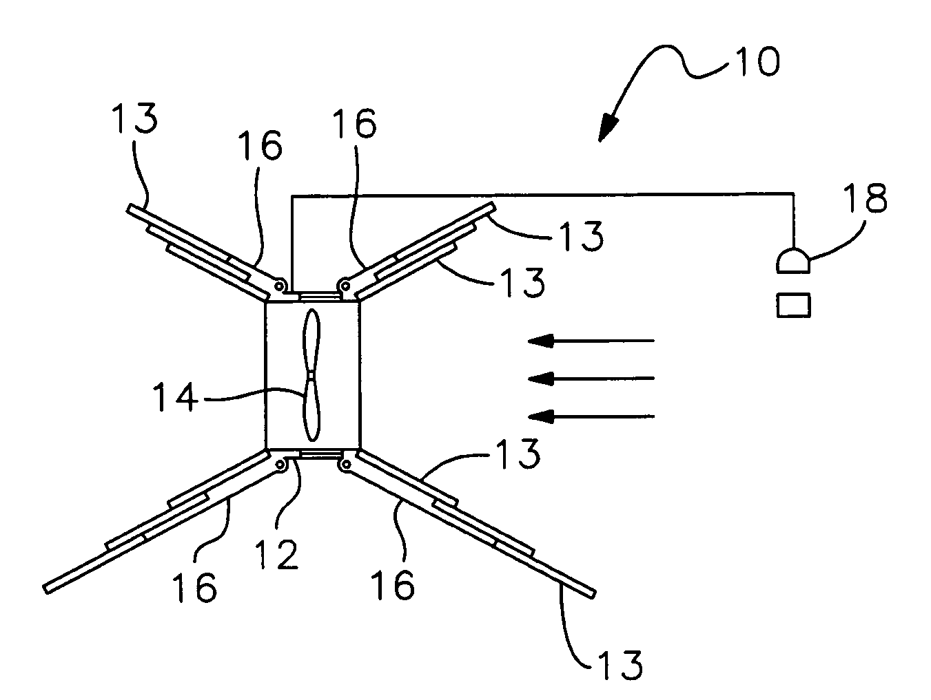
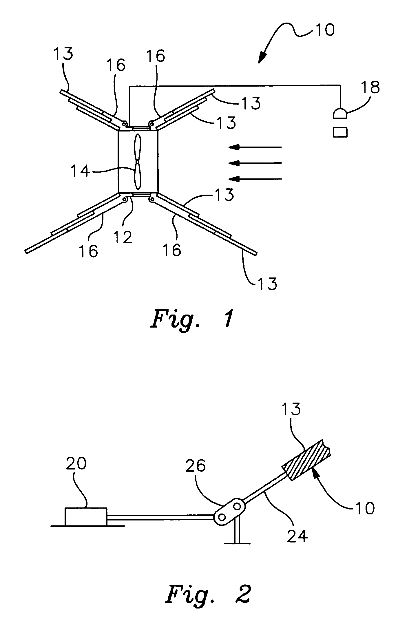
[0016]Referring to the figures, FIG. 1 illustrates a perspective view of a multidirectional hydrokinetic power generating turbine 10 according to a preferred embodiment of the present application. Multidirectional hydrokinetic power generating turbine 10 includes an impeller housing 12, an impeller 14 disposed within the impeller housing 14, adjustable ducts 16 pivotally connected to impeller housing 12, and a plurality of duct leafs 13 disposed about the one or more adjustable ducts 16. Duct leafs 13 articulate to cause the one or more adjustable ducts 16 to converge and diverge for selectively disposing a fluid about one or more impellers 14. Adjustable ducts 16 may be considered to be as an inflow duct or an outflow duct, depending on the direction of in which the fluid is disposed.

[0017]A sensor 18 operably associates with multidirectional hydrokinetic power generating turbine 10 to vary the positioning and / or degree of extension and retraction of adjustable ducts 16. As fluid i...


PUM


Abstract

A multidirectional hydrokinetic power generating turbine has an impeller housing with one or more impellers disposed within the impeller housing, one or more adjustable ducts pivotally connected to the impeller housing, and a plurality of duct leafs disposed about the one or more ducts. The plurality of duct leafs articulate and cause the one or more adjustable ducts to converge and diverge to selectively disposing a fluid about the one or more impellers.

Description

CROSS REFERENCE TO RELATED APPLICATIONS[0001]This application claims the benefit of U.S. Provisional Application No. 60 / 995,774, filed 28 Sep. 2007, and titled “A machine for increased hydro power generation and process for optimal control of pressure drop across an in situ ducted hydro kinetic turbine.”BACKGROUND OF THE INVENTION[0002]1. Field of the Invention[0003]The present invention relates to hydrokinetic power generating turbines. In particular, the present invention relates to multidirectional hydrokinetic power generating turbines that include adjustable ducting and stators.[0004]2. Description of Related Art[0005]Conventional hydropower systems have employed a variety of devices to attain optimal usage of fluid flow. Some hydropower systems currently include ducts with wide inputs and a variety of outputs to capture the maximum amount of flow channeled to the impellers situated in a current. Other hydropower systems employ less expansive ducting in hopes of building head s...

Claims


Application Information

Patent Timeline
Patent Type & Authority Applications(United States)
IPC IPC(8): F03B3/18F03B15/02F03B15/06F03B3/14
CPCF03B3/18F03B15/02F03B17/061Y02E10/28Y02E10/223Y02E10/226F05B2240/133Y02E10/20
Inventor KROUSE, WAYNE F.
Owner HYDRO GREEN ENERGY LLC
Why Eureka
Try Eureka