
Display substrate manufacturing method and vacuum processing apparatus

a substrate and vacuum processing technology, applied in the direction of electrode system manufacture, electrode system exhaustion, electrode system manufacturing, etc., can solve the problems of increasing the demerit of the work of removing deteriorating the clamping performance, and unrealistic removal of the electrostatic clamping from the completed substrate processing apparatus. achieve the effect of simple method

Inactive Publication Date: 2009-04-02
CANON ANELVA CORP
View PDF5 Cites 12 Cited by
  • Summary
  • Abstract
  • Description
  • Claims
  • Application Information

AI Technical Summary

Benefits of technology

The present invention provides a method and apparatus for manufacturing display substrates, which can quickly and easily remove foreign particles that may stick to the substrate during the manufacturing process. This is achieved by placing a dummy substrate on the clamping surface of the manufacturing apparatus, heating the base of the apparatus, and using an evacuating means to bring the dummy substrate into tight contact with the clamping surface. The method and apparatus can improve the efficiency and quality of the display substrate manufacturing process.

Problems solved by technology

The clamping performance deteriorates when a contaminant adheres to the clamping surface of the electrostatic clamping.
Unfortunately, it is unrealistic to remove the electrostatic clamping from the completed substrate processing apparatus because an enormous work scale is required.
This further increases the demerit of the work of removing the electrostatic clamping.
Unfortunately, the electrostatic clamping having the arrangement shown in FIG. 3 increases the apparatus cost because an additional function such as a coating must be formed in the arrangement of the electrostatic clamping.
Accordingly, the cost of a coating or the like also significantly increases.
However, almost no effect of removing foreign particles sticking to the clamping surface of the electrostatic clamping can be expected.

Method used


Image

  • Display substrate manufacturing method and vacuum processing apparatus
  • Display substrate manufacturing method and vacuum processing apparatus
  • Display substrate manufacturing method and vacuum processing apparatus

Examples


Embodiment Construction

[0025]Embodiments of the present invention will be explained below with reference to the accompanying drawings.

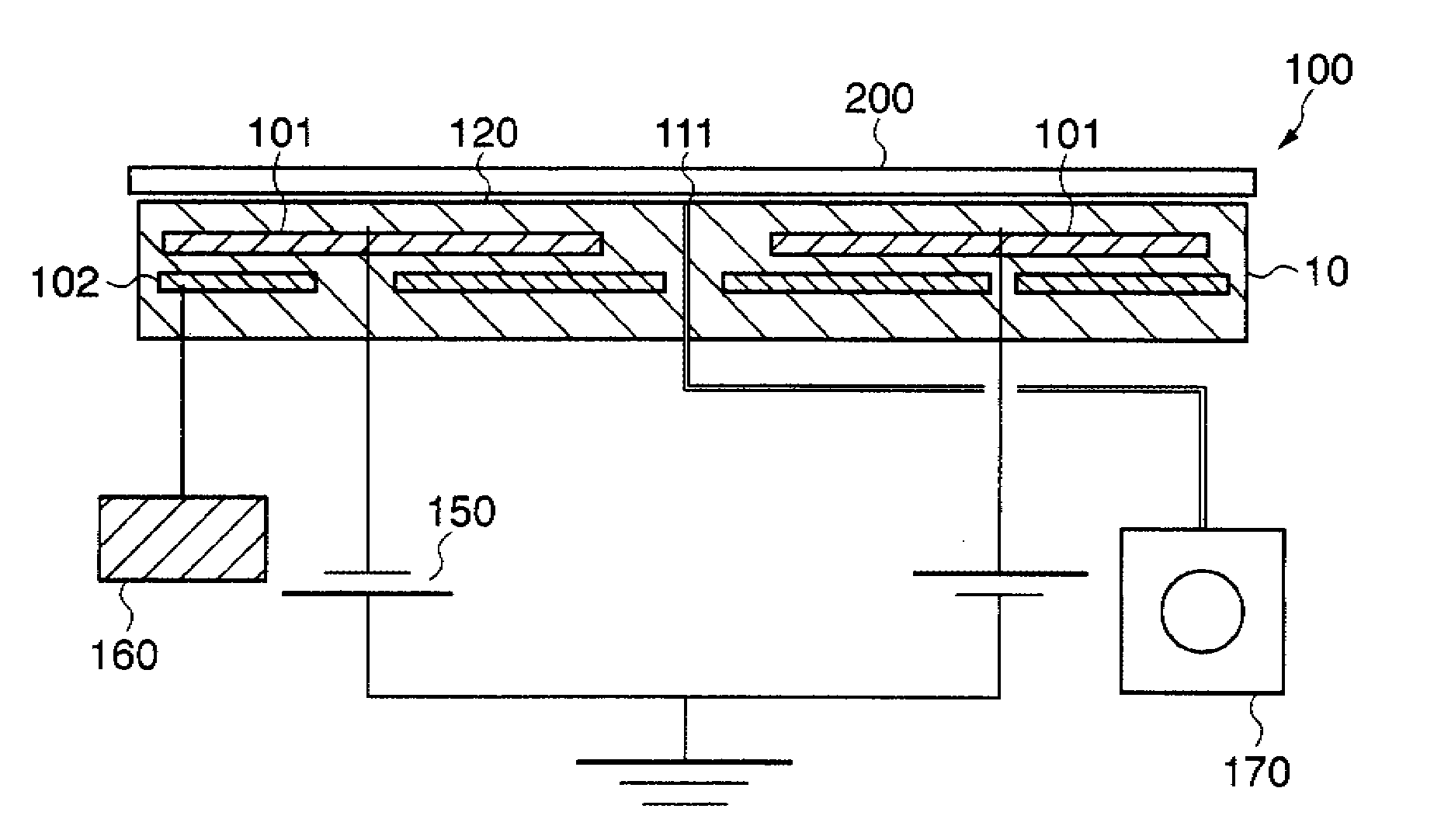
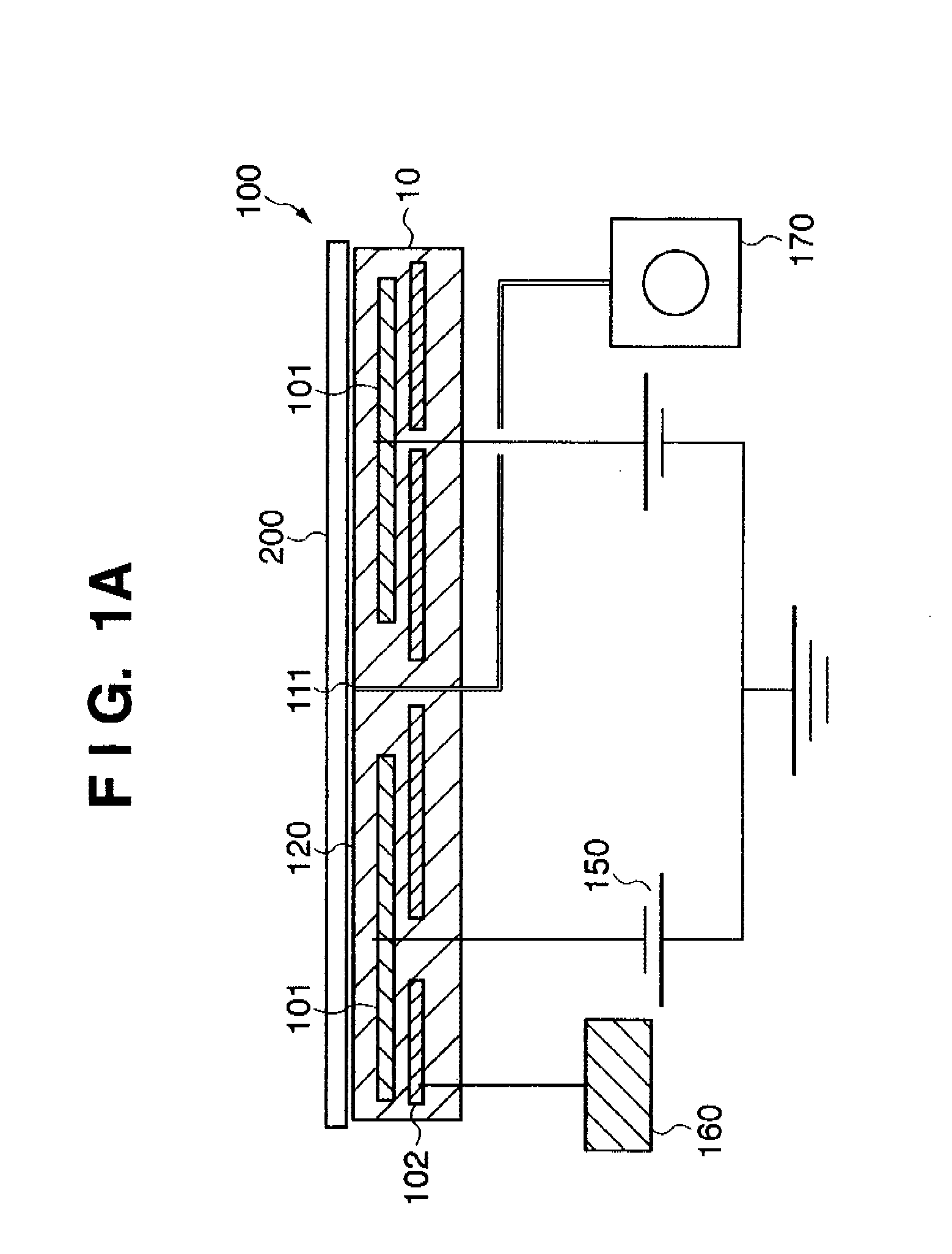
[0026]FIG. 1A is a sectional view showing an outline of the arrangement of an electrostatic clamping forming a display substrate manufacturing apparatus according to an embodiment of the present invention.

[0027]A base 10 of an electrostatic clamping 100 forming the display substrate manufacturing apparatus incorporates a clamping electrode 101 for generating an electrostatic clamping force on a clamping surface 120, and a built-in heater 102 as a heating means for heating the electrostatic clamping 100. The clamping electrode 101 is electrically connected to a clamping power supply 150, and the built-in heater 102 is electrically connected to a built-in heater power supply 160. These power supplies supply electric power. The clamping electrode 101 and the clamping power supply 150 function as an electrostatic clamping force generating means for generating an electrostatic c...


PUM


Abstract

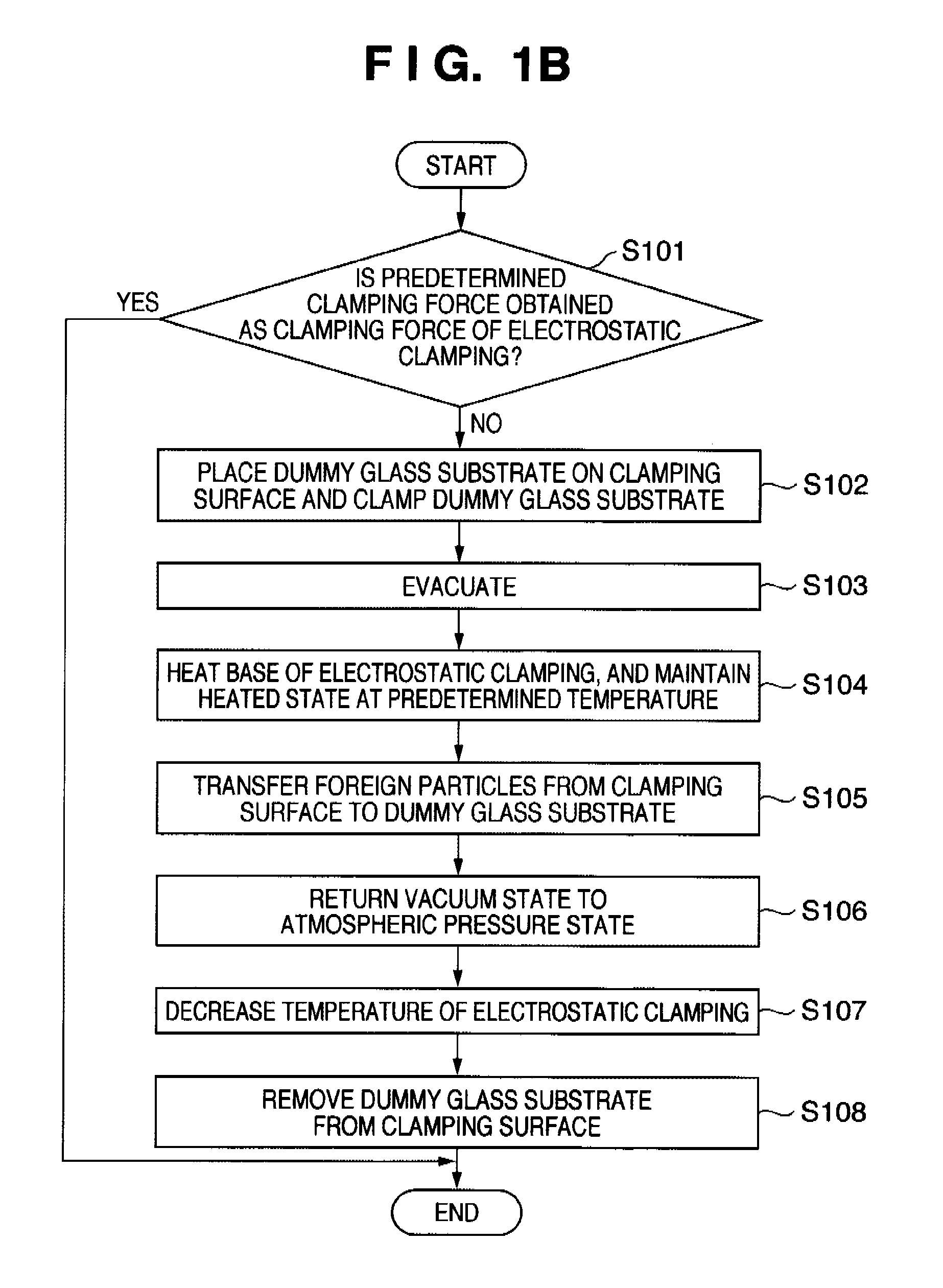
A display substrate manufacturing method includes a placing step of placing a dummy substrate on a clamping surface, an evacuating step of evacuating the interior of a space formed between the clamping surface and dummy substrate, in order to bring the dummy substrate into tight contact with the clamping surface, a heating step of heating a base in order to facilitate removing, from the clamping surface, foreign particles sticking to the clamping surface, a transferring step of transferring the foreign particles sticking to the clamping surface from the clamping surface to the dummy substrate in tight contact with the clamping surface, and a removing step of removing, from the clamping surface, the dummy substrate to which the foreign particles are transferred in the transferring step.

Description

BACKGROUND OF THE INVENTION[0001]1. Field of the Invention[0002]The present invention relates to a method of manufacturing a display substrate such as a flat panel display, and a vacuum processing apparatus.[0003]2. Description of the Related Art[0004]An electrostatic clamping is used as a means for fixing a substrate to be processed in a substrate processing apparatus such as a semiconductor manufacturing apparatus or flat panel display manufacturing apparatus. In a substrate processing apparatus like this, processing is performed in a state in which a substrate is fixed on the electrostatic clamping by its electrostatic clamping force. After the processing is completed, the substrate is released from the electrostatic clamping by removing the electrostatic clamping force. Thus, substrates are repetitively clamped to and released from the electrostatic clamping in the substrate processing apparatus having the electrostatic clamping.[0005]On the clamping surface of the electrostatic...

Claims


Application Information

Patent Timeline
Patent Type & Authority Applications(United States)
IPC IPC(8): H01J9/38H01J9/385
CPCH01L21/6831H01L21/67028
Inventor INOUE, MASATOMATSUI, SHIN
Owner CANON ANELVA CORP
Learn More