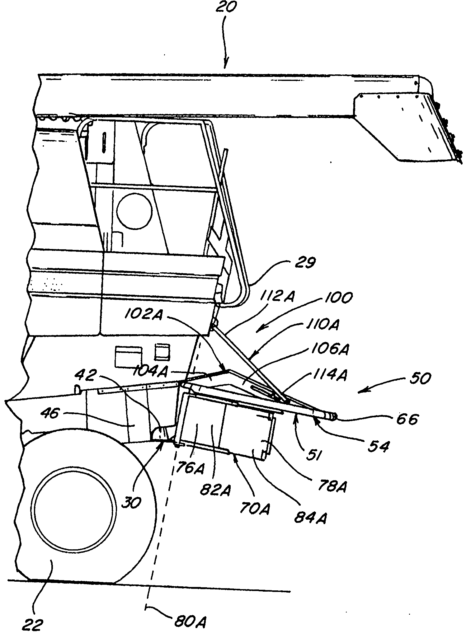
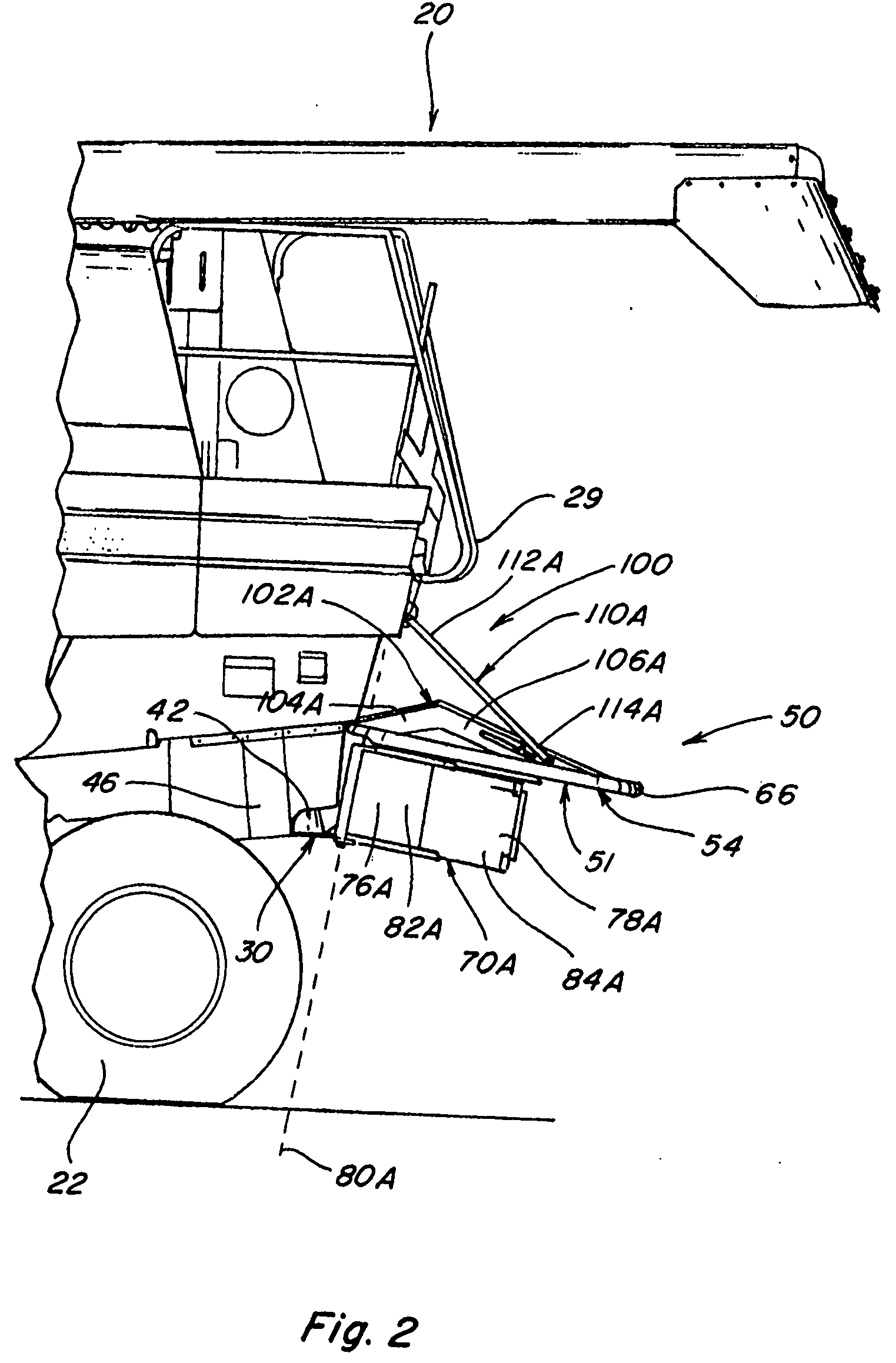
Windrow forming construction

a technology of forming construction and windrows, applied in the direction of mowers, agriculture tools and machines, agriculture, etc., can solve the problems of less than ideal windrow formation, increased drying time, and lower positioning of tines

Inactive Publication Date: 2009-04-02
BLUE LEAF I P
View PDF21 Cites 14 Cited by
  • Summary
  • Abstract
  • Description
  • Claims
  • Application Information

AI Technical Summary

Benefits of technology

[0021]As will be further evident from the drawings herewith, which drawings representationally depict various of the more significant elements and features of preferred embodiments but which should not necessarily be considered to scale, and the accompanying description that follows, the present invention thus discloses a new and improved construction and technique for better forming wind

Problems solved by technology

With many of the various windrowing techniques employed and the constructions utilized to produce a windrow, the resulting windrow has been somewhat unevenly distributed behind the combine, instead of as a cohesive mat, and the crop residue forming the windrow has sometimes been blown or pressed downwardly into and against the stubble rem

Method used


Image

  • Windrow forming construction
  • Windrow forming construction
  • Windrow forming construction

Examples


Embodiment Construction

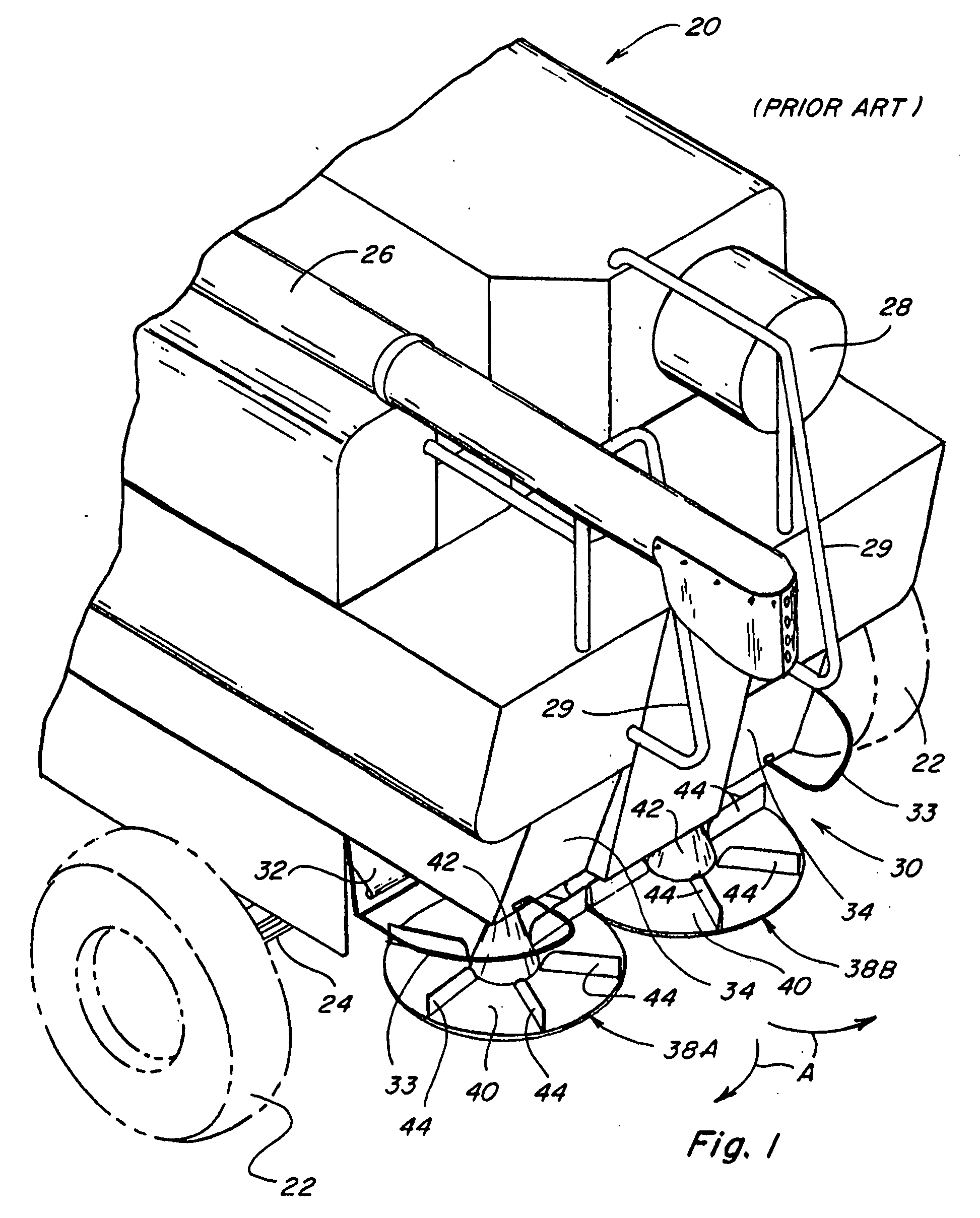
[0033]Referring now to the drawings, wherein like numerals refer to generally like or similar items and wherein certain numerals may be applied on a representational basis to selected, representative items of a class of like items instead of to all of the depicted like items, FIG. 1 depicts the rear portion of a typical combine 20 having a pair of rear tires 22 mounted upon a rear axle 24, with a grain auger or threshing rotor 26, an engine radiator air screen 28, and handrails 29 mounted upon the upper structure of the combine 20. A spreader assembly 30, of well known construction, is mounted generally below a crop residue discharge chute 32. For safety and other purposes, guard bars 33 are mounted extending generally over and across certain more exposed portions of the spreader assembly 30 and removable drive linkage cover plates 34 enclose associated drive linkages. When the threshing rotor 26 is operating, crop residue from such operation is discharged into discharge chute 32 wh...


PUM


Abstract

A windrow forming construction mountable at the rear of a combine above the level of a spreader assembly, such construction extending rearwardly from the combine to beyond the rear extent of the spreader assembly footprint and laterally across the expanse of the spreader assembly footprint and being adjustably positionable to vary the inclination thereof relative to the ground surface, the construction including side deflectors disposed at opposite sides of the construction so as to control to some extent the sidewardly distribution of the crop residue, which side deflectors are laterally pivotable about generally vertical axes to vary the spacing between the free ends thereof and are also longitudinally extendable so as to channel to some extent the crop residue towards the space between the free ends, and a positioning mechanism operable to vary the inclination of such construction relative to the ground surface so as to control to some extent the degree with which the crop residue is directed into the stubble remaining on the field and to support the construction in such position.

Description

TECHNICAL FIELD[0001]The present invention relates generally to a construction for controlling and channeling the discharge of crop residue from an agricultural combine, and more particularly to the provision of a windrow forming construction for use in forming windrows of crop residue behind the combine as a crop is harvested.BACKGROUND ART[0002]Axially arranged rotary threshing or separating systems have long been in use in agricultural combines for threshing crops to separate grain from crop residue, also referred to as material other than grain (MOG). Such axially arranged systems typically include at least one cylindrical rotor rotated within a concave or cage, the rotor and surrounding concave being oriented so as to extend forwardly to rearwardly within the combine.[0003]In operation, crop material is fed or directed into a circumferential passage between the rotor and the concave, hereinafter referred to as a rotor residue passage, and is carried rearwardly along a generally...

Claims


Application Information

Patent Timeline
IPC IPC(8): A01F12/00
CPCA01D41/1243
Inventor MURRAY, CRAIG E.LANDUYT, KOEN
Owner BLUE LEAF I P
Why Eureka
Try Eureka