Self-Locating Sensor Mounting Apparatus

a self-mounting and sensor technology, applied in the field of self-mounting mounting apparatuses, can solve the problems of uneven expansion, large variation in the size and shape of the human head, and the sensor in the mounting apparatus which is entirely elastic, and achieve the effect of careful measurement and accurate placement of the sensor

Active Publication Date: 2009-04-02
QUANTUM APPLIED SCI & RES
View PDF27 Cites 86 Cited by
  • Summary
  • Abstract
  • Description
  • Claims
  • Application Information

AI Technical Summary

Benefits of technology

[0011]With this construction, the present invention allows for accurate placement of sensors or other objects by a person with no specific training or skill, and eliminates the need for careful measurements of an individual subject's head. The advantages of the present invention lend itself to a variety of applications, such as medical dia

Problems solved by technology

The technical challenge is that the size and shape of the human head can vary significantly.
However, in practice, expandable mounting apparatuses such as hat body 2 shown in FIG. 1 become caught on parts of the head and the expansion is uneven.
In addition, sensors in mounting apparatuses which are entirely elasticized are prone to become tilted, i.e., they do not

Method used


Image

  • Self-Locating Sensor Mounting Apparatus
  • Self-Locating Sensor Mounting Apparatus
  • Self-Locating Sensor Mounting Apparatus

Examples


first embodiment

[0040]Circumferential band 122 preferably includes one or more adjustment mechanism means 138. In the embodiment depicted in FIG. 11, adjustment means 138 in the form of an adjustable band 144 and a plurality of VELCRO straps indicated at 145. When mounting apparatus 110 is positioned on a subject's head as shown, spring assemblies 114 bias mounting units 116 and associated electrodes 118 against a subject's head, providing an upward force against the subject. In order to counter this force, a retaining member in the form of a padded retaining arm assembly 146 is provided. Retaining arm assembly 146 is adapted to be positioned behind the ears of a subject in order to provide a downward force to mounting apparatus 110 and preferably includes an adjustable rear band 148 to allow for further customization of mounting apparatus 110. A plurality of communication and power wires 184 connect electrodes 118 to a control apparatus and battery source in the same manner as discussed with refer...

second embodiment

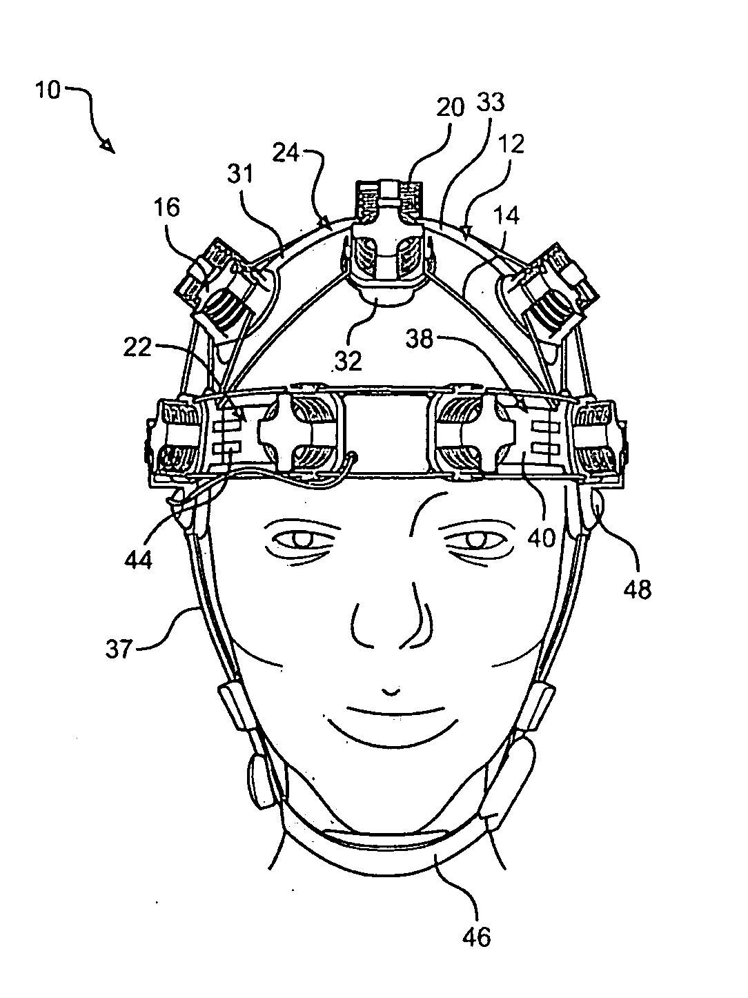
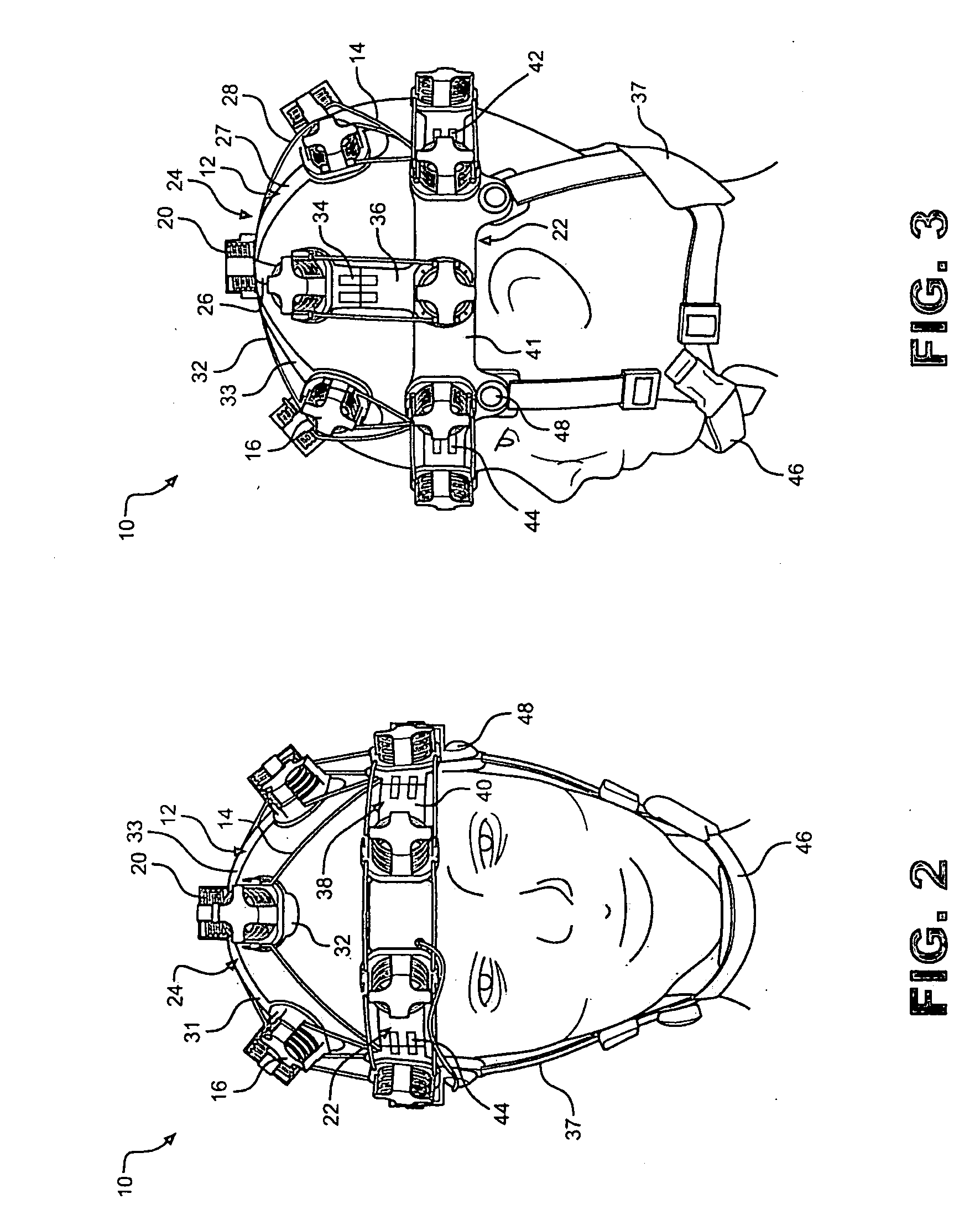
[0041]The advantages of the present invention lend itself to a variety of applications. In an alternative embodiment of the present invention depicted in FIGS. 13-15 for example, a mounting apparatus 210 is adapted to be incorporated into a helmet, such as a military helmet (not shown). Similar to the second embodiment, mounting apparatus 210 includes eight non-elastic inextensible elements or arms 212 and biasing elements in the form of spring assemblies (not shown), which bias arms 212 towards a subject's head. A plurality of mounting units 216 are connected to arms 212 and are adapted to house objects such as impact sensors 218. Principle elements of mounting apparatus 210 include a circumferential band 222 that fits around the widest part of a subject's head, and a petal element or central mount 224 that sits on top of the head. Like arms 112, arms 212 are rigid, and are attached to central mount 224 via rotating joints 225. In use, arms 212 are biased against a subject's head v...


PUM


Abstract

A self-locating mounting apparatus for holding objects such as sensors at specific positions on a subject's head includes a central mount constituted by a plurality of inextensible elements adapted to fit over the top of a subject's head. In addition, the mounting apparatus includes an adjustable circumferential band adapted to circle the subject's head and connect the central mount to inextensible side elements via sliding joints. A plurality of biasing elements provide a force for biasing sensor mounting units on the mounting apparatus against a subject's head, allowing for long-term sensing while minimizing interference forces on the mounting units. Advantageously, the mounting apparatus holds sensors within approximately 5 mm of their desired measurement positions over a range of subject head sizes.

Description

CROSS-REFERENCE TO RELATED APPLICATIONS[0001]The present application claims the benefit of U.S. Provisional Patent Application Ser. No. 60 / 960,472 entitled “Self Locating Mounting apparatus for Holding Objects on the Head” filed Oct. 1, 2007.STATEMENT REGARDING FEDERALLY SPONSORED RESEARCH AND DEVELOPMENT[0002]This invention was made and developed under Contract No. W91ZLK-04-P-0235 awarded by the Army. The Government has a fully paid up non-exclusive license in this invention.BACKGROUND OF THE INVENTION[0003]1. Field of the Invention[0004]The present invention pertains to the art of sensing devices and, more particularly, to a self-locating mounting apparatus in the form of headgear for accurately positioning sensors on a subject, such as for medical purposes.[0005]2. Discussion of the Prior Art[0006]There are a number of applications in which it is necessary to place sensors on the scalp of a human subject at defined locations relative to the head. One principle application is in ...

Claims


Application Information

Patent Timeline
IPC IPC(8): A61B5/0476A61B5/00
CPCA61B5/0478A61B5/0002A61B5/291
Inventor TURNER, PETER JAMESMATTHEWS, ROBERTWOODWARD, JAMISON SCOTTERMOLAEV, KONSTANTINE V.HIBBS, ANDREW D.
Owner QUANTUM APPLIED SCI & RES
Why Eureka
Try Eureka