Zoom microscope

a microscope and zoom technology, applied in the field of zoom microscopes, can solve the problem that the self-fluorescence generated in the observation variable-power optical system becomes a nois

Inactive Publication Date: 2009-04-09
NIKON CORP
View PDF9 Cites 13 Cited by
  • Summary
  • Abstract
  • Description
  • Claims
  • Application Information

AI Technical Summary

Benefits of technology

[0014]The present invention can provide a zoom microscope which can perform

Problems solved by technology

However, in the zoom microscope disclosed in Patent Document 1, because during fluorescence observation, illumination light which is excitation light, passes through the observation variable-power optical system, a problem arises that self-fluorescence generated in the observation variable-power optical sys

Method used


Image

  • Zoom microscope
  • Zoom microscope
  • Zoom microscope

Examples


example

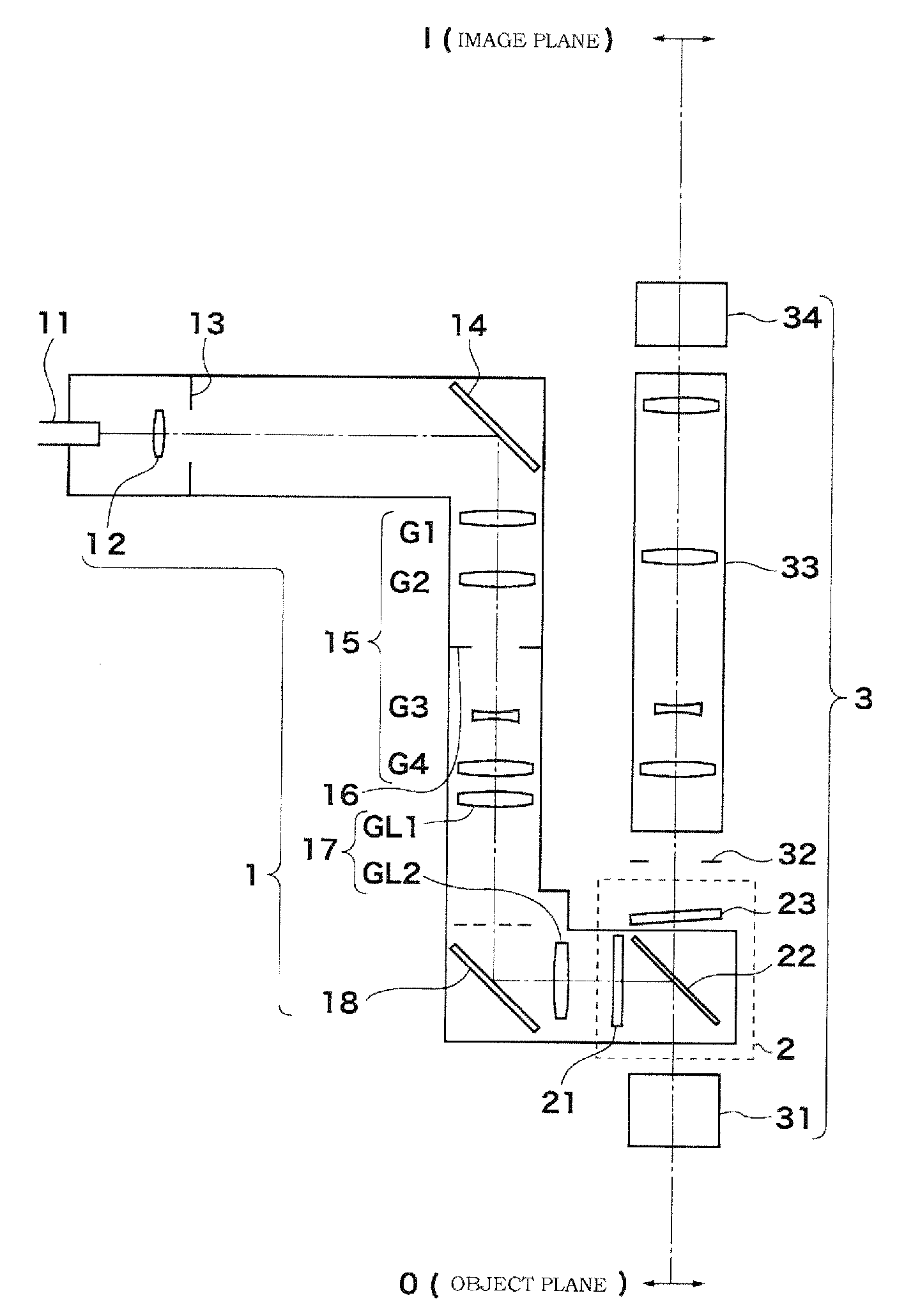
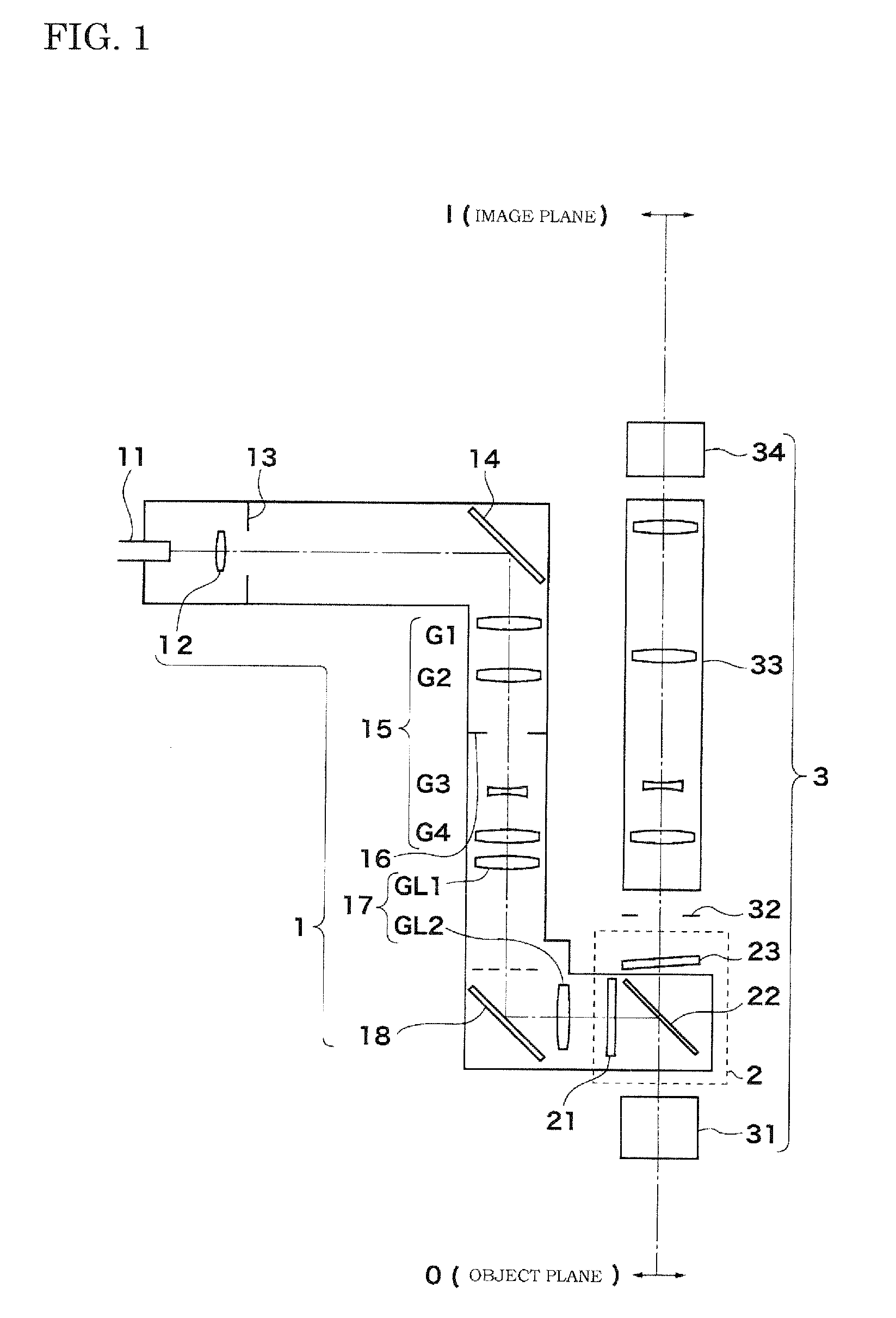
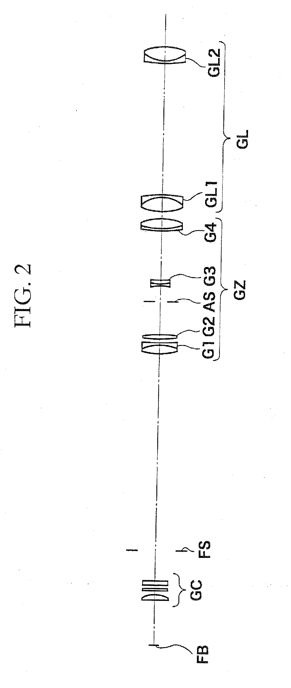
[0056]FIG. 2 shows an example of an arrangement of the lens system in the zoom epi-illumination optical system of FIG. 1. In FIG. 2, the folding mirrors are omitted, and the lenses are linearly disposed. The lens system includes a collector lens group GC (corresponding to the collector lens 12 of FIG. 1), a field stop FS (corresponding to the field stop 13 of FIG. 1), a variable-power optical system GZ (corresponding to the zoom optical system 15 of FIG. 1), and a relay optical system GL (corresponding to the relay optical system 17 of FIG. 1), arranged in the order described above from the side of the light source FB. The collector lens group GC includes a planoconvex lens whose plane portion is oriented toward the side of the light source FB, an ultraviolet cut filter, and an infrared cut filter. The variable-power optical system GZ includes a first lens group G1 (corresponding to the first lens group G1 of FIG. 1) formed by a cemented lens of a biconvex lens and a biconcave lens,...


PUM


Abstract

A zoom microscope includes an observation optical system having an exchangeable objective lens, an aperture diaphragm, an afocal zoom system, and an image forming optical system; and a zoom epi-illumination optical system. The zoom epi-illumination optical system has an optical path which is also the optical path of the observation optical system between the objective lens and the afocal zoom system so as to illuminate an object by incident light. In the zoom epi-illumination optical system, an image of a light source is formed in the vicinity of the pupil position of the objective lens. This realizes a zoom microscope capable of performing fluorescent epi-illumination without shading in all the magnification ranges.

Description

TECHNICAL FIELD[0001]The present invention relates to a zoom microscope.BACKGROUND ART[0002]Conventionally, as disclosed in Patent Documents 1 to 4, there are known zoom microscopes which illuminate an object through an objective lens. In the zoom microscope disclosed in Patent Document 1, an object is illuminated through an objective lens and an observation variable-power optical system. Each of the zoom microscopes disclosed in Patent Documents 1 to 4 includes an illumination optical system which is independent of an observation variable-power optical system, and an object is illuminated through an objective lens.Patent Document 1: Japan Kokai Patent Document No. 11-231227Patent Document 2: Japan Kokai Patent Document No. 9-274141Patent Document 3: Japan Kokai Patent Document No. 2001-516071Patent Document 4: Japan Kokai Patent Document No. 2005-157335[0003]However, in the zoom microscope disclosed in Patent Document 1, because during fluorescence observation, illumination light w...

Claims


Application Information

Patent Timeline
IPC IPC(8): G02B21/02
CPCG02B21/16G02B21/025
Inventor SUZUKI, FUMIO
Owner NIKON CORP
Why Eureka
Try Eureka