Turbocharger with variable nozzle mechanism

a variable nozzle and turbocharger technology, applied in the field of turbochargers, can solve the problems of water freezing, affecting the operation of the nozzle vanes, and the deformation of the variable nozzle mechanism,

Inactive Publication Date: 2009-04-09
TOYOTA IND CORP +1
View PDF6 Cites 41 Cited by
  • Summary
  • Abstract
  • Description
  • Claims
  • Application Information

AI Technical Summary

Benefits of technology

[0005]Accordingly, it is an objective of the present invention to provide a turbocharger having a variable nozzle mechanism that prevents a nozzle vane drive mechanism from being damaged by frozen water.

Problems solved by technology

If the variable nozzle mechanism thermally expands and interferes with the turbine housing after the engine has been started, the variable nozzle mechanism may deform and hamper proper operation of the nozzle vanes.
However, if the engine is stopped under a low temperature immediately after the engine has been started, the water may be frozen.
This hinders the nozzle vane drive mechanism from operating.
Thus, if the engine is re-started in this state, the nozzle vane drive mechanism may be damaged.

Method used


Image

  • Turbocharger with variable nozzle mechanism
  • Turbocharger with variable nozzle mechanism
  • Turbocharger with variable nozzle mechanism

Examples


first embodiment

[0015]the present invention will now be described with reference to FIGS. 1 to 5.

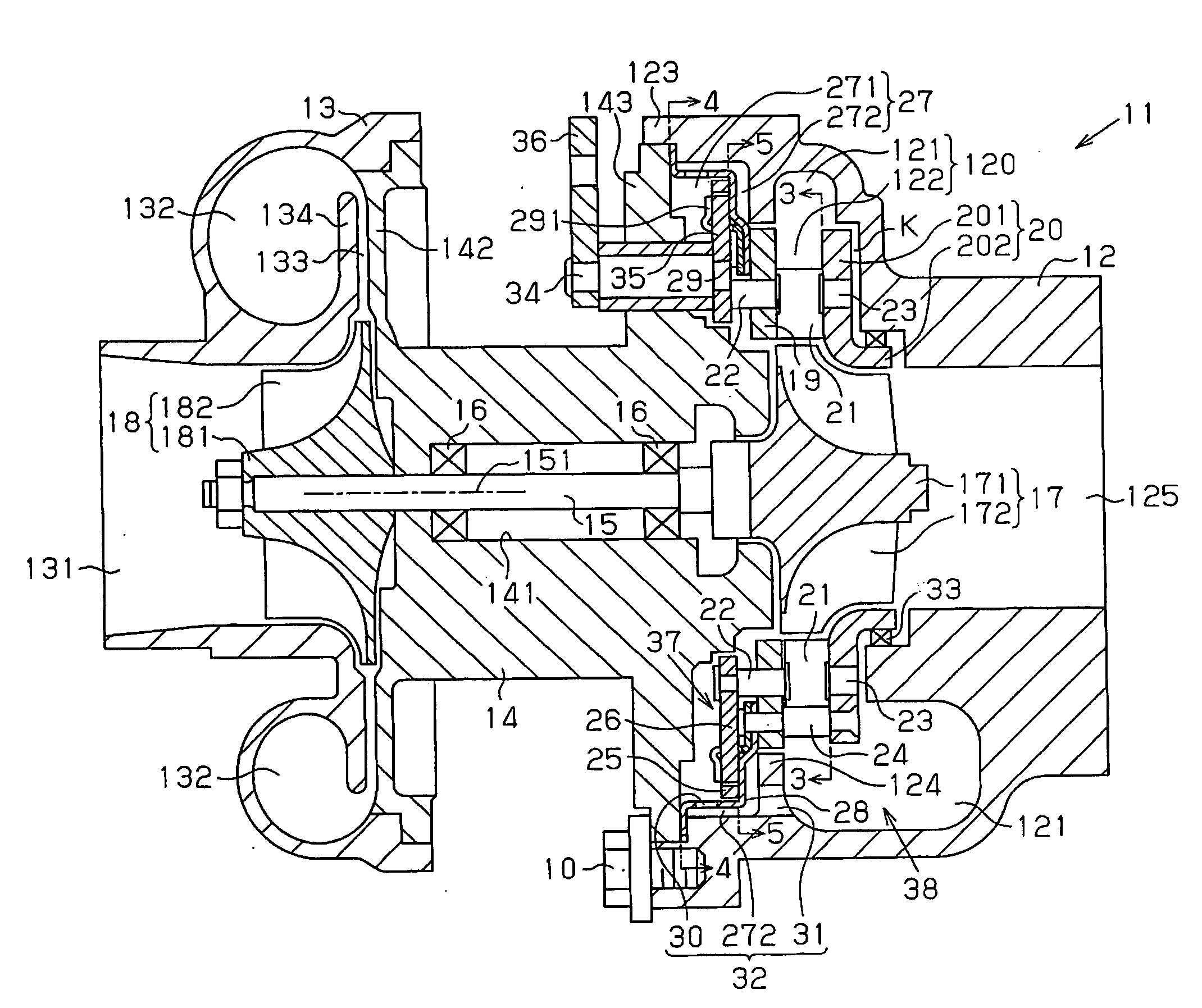
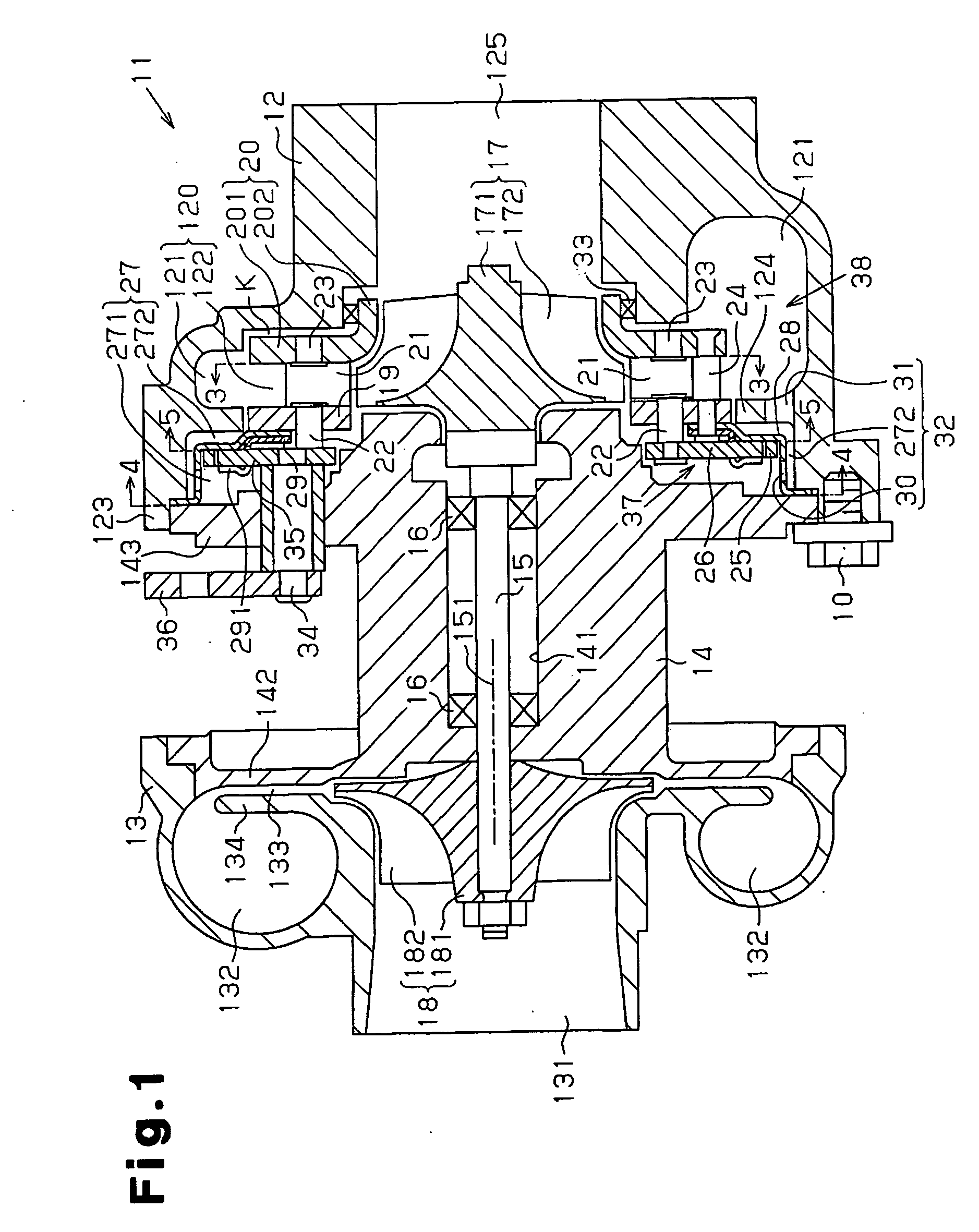
[0016]As shown in FIG. 1, a turbocharger 11 includes a turbine housing 12, a compressor housing 13, and a center housing 14. The turbine housing 12 is arranged in an exhaust passage (not shown) of an internal combustion engine (not shown). The compressor housing 13 is arranged in an intake passage (not shown) of the engine. The center housing 14 connects the turbine housing 12 to the compressor housing 13. A connecting cylindrical portion 123 is formed integrally with the turbine housing 12, and a flange wall 143 is formed integrally with the center housing 14. The flange wall 143 is engaged with the connecting cylindrical portion 123. Specifically, the flange wall 143 is connected to the connecting cylindrical portion 123 through a screw 10 threaded into the connecting cylindrical portion 123 so that the flange wall 143 does not separate from the connecting cylindrical portion 123. This arrangement con...

second embodiment

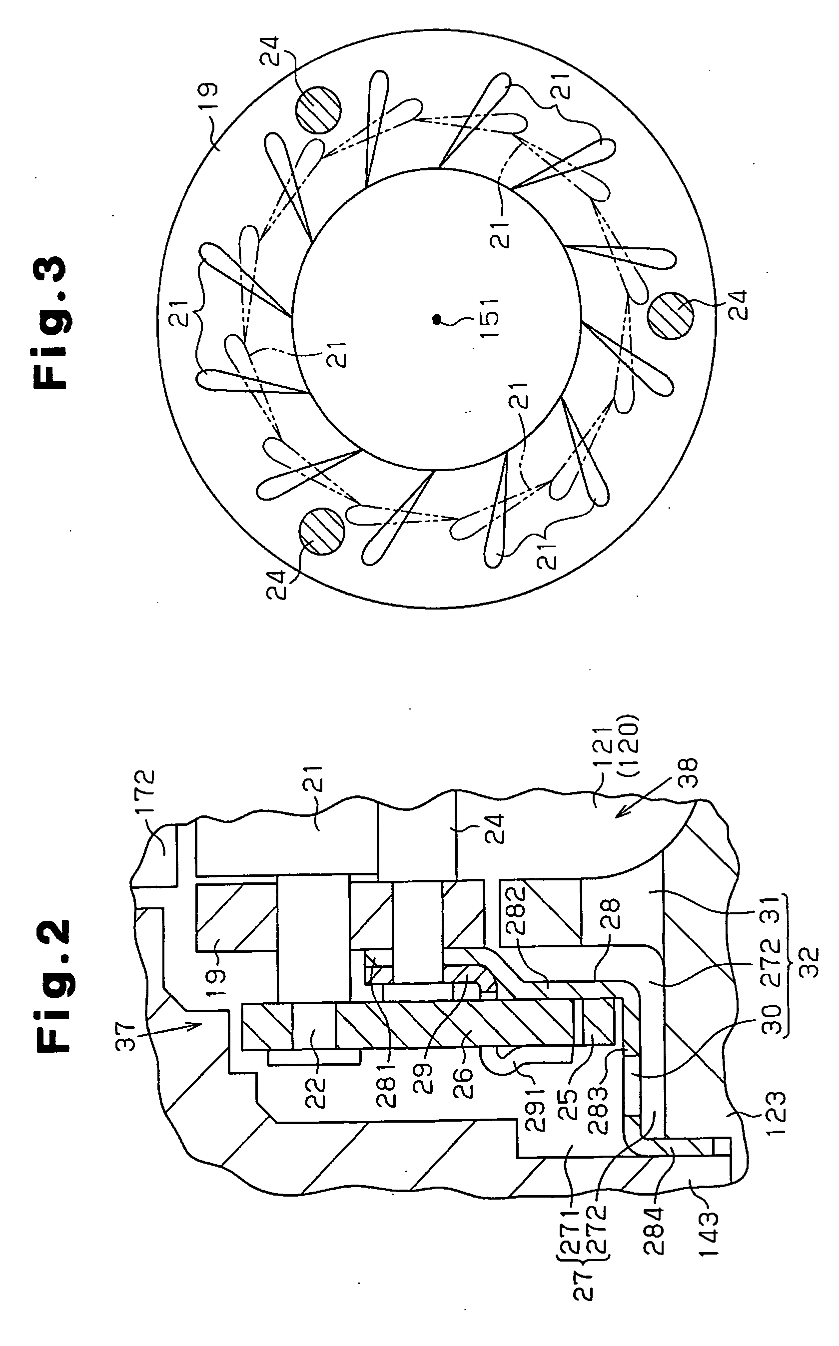
[0044]In the second embodiment, the outer circumferential surface of the cylindrical portion 233 of the support ring 28 contacts the inner circumferential surface of the connecting cylindrical portion 123 of the turbine housing 12 in a surface-contact manner. A groove 39, or a portion of a drain passage 32A connected to the gas passage 120, extends in the axial direction along the inner circumferential surface of the connecting cylindrical portion 123.

[0045]The second embodiment has advantages equivalent to those of the first embodiment.

[0046]The present invention may be embodied in the following forms.

[0047]In the first embodiment, a plurality of drain holes 30 may be provided.

[0048]In the first embodiment, a plurality of drain holes 31 may be arranged.


PUM


Abstract

A turbocharger having a variable nozzle mechanism, which is accommodated in an accommodating chamber, is disclosed. The variable nozzle mechanism has a nozzle ring, a nozzle vane, a nozzle vane drive mechanism, and a support ring. The nozzle ring defines a gas passage through which exhaust gas is guided to a turbine wheel. The nozzle vane is supported by the nozzle ring and varies the flow area of the gas passage. The nozzle vane drive mechanism drives the nozzle vane. The support ring is connected to the nozzle ring. The nozzle vane drive mechanism is accommodated in the accommodating chamber as spaced from the nozzle ring through the support ring. The turbocharger has a drain passage that extends through a lower portion of the support ring and reaches the gas passage. The drain passage is located downward from the nozzle vane drive mechanism.

Description

FIELD OF THE INVENTION[0001]The present invention relates to a turbocharger having a turbine housing accommodating a turbine wheel rotated by receiving exhaust gas blown onto the turbine wheel from an internal combustion engine and a variable nozzle mechanism.[0002]Japanese Laid-Open Patent Publication No. 2006-125588 discloses a turbocharger having a variable nozzle mechanism. The variable nozzle mechanism regulates the flow rate of the exhaust gas blown onto a turbine wheel accommodated in a turbine housing through selective opening and closing of a plurality of nozzle vanes arranged in a gas passage. The variable nozzle mechanism includes a nozzle ring and a nozzle vane drive mechanism. The nozzle vane drive mechanism includes a rotatable unison ring and a plurality of arms, which pivot when the unison ring rotates. Specifically, when the arms pivot as the unison ring rotates, the nozzle vanes, which are connected to the arms, pivot. A support ring is provided between the nozzle ...

Claims


Application Information

Patent Timeline
Patent Type & Authority Applications(United States)
IPC IPC(8): F01D17/16
CPCF01D17/165F01D25/02F05D2260/602F05D2220/40F02C6/12
Inventor YASUI, TOMOHIROFUJITA, SHUICHIKAWAMOTO, MASUOISOGAI, TOMOYUKI
Owner TOYOTA IND CORP
Why Eureka
Try Eureka