
Method and apparatus for calibrating gyro-sensor

a gyrosensor and gyro-sensor technology, applied in the field of gyro-sensor calibration methods and apparatuses, can solve the problems of increasing manufacturing costs, not cost-effective when applied to mobile robots requiring cost competitiveness, and high-priced gyro-sensors. the effect of location estimation efficiency

Active Publication Date: 2009-04-09
SAMSUNG ELECTRONICS CO LTD
View PDF4 Cites 24 Cited by
  • Summary
  • Abstract
  • Description
  • Claims
  • Application Information

AI Technical Summary

Benefits of technology

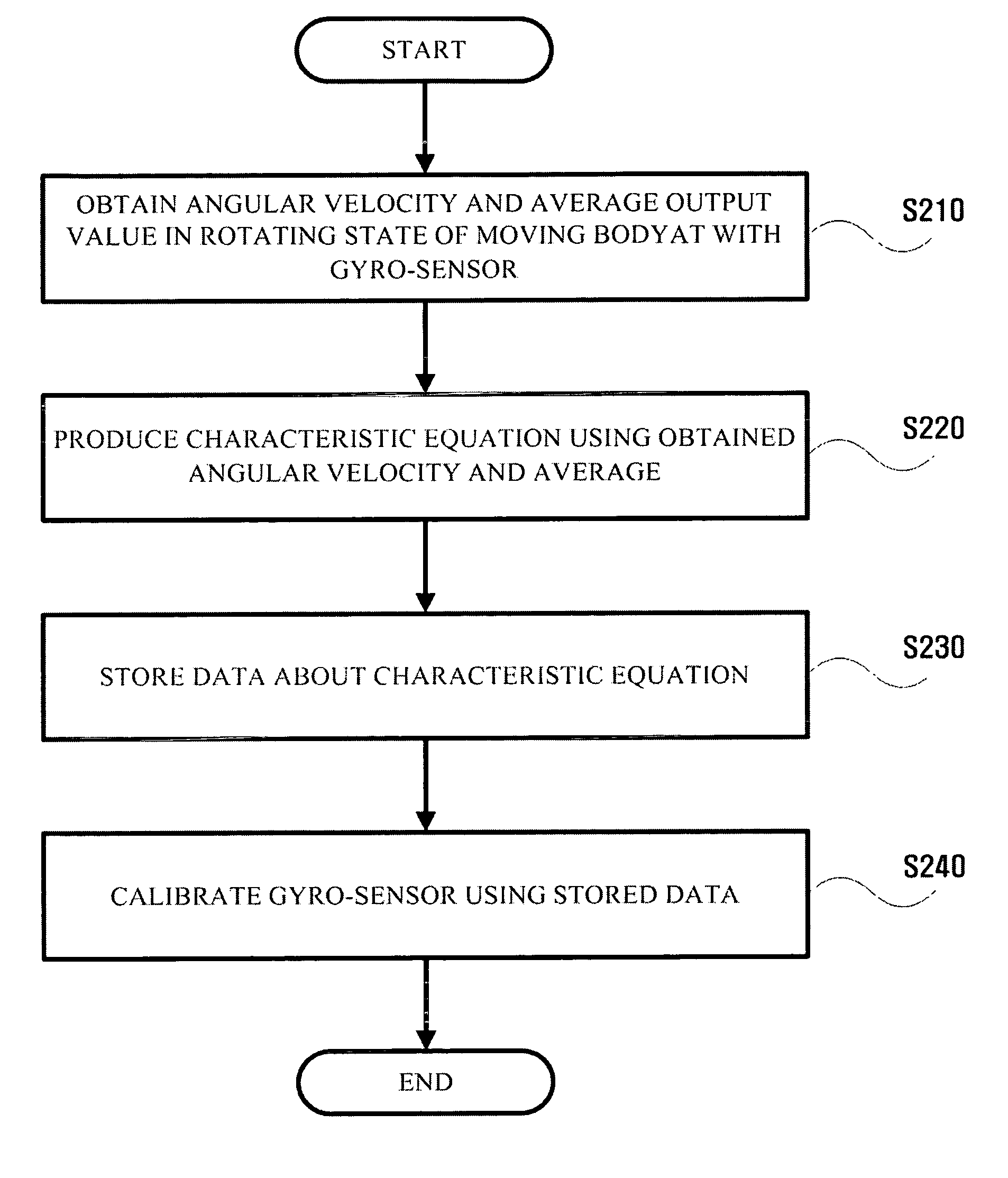
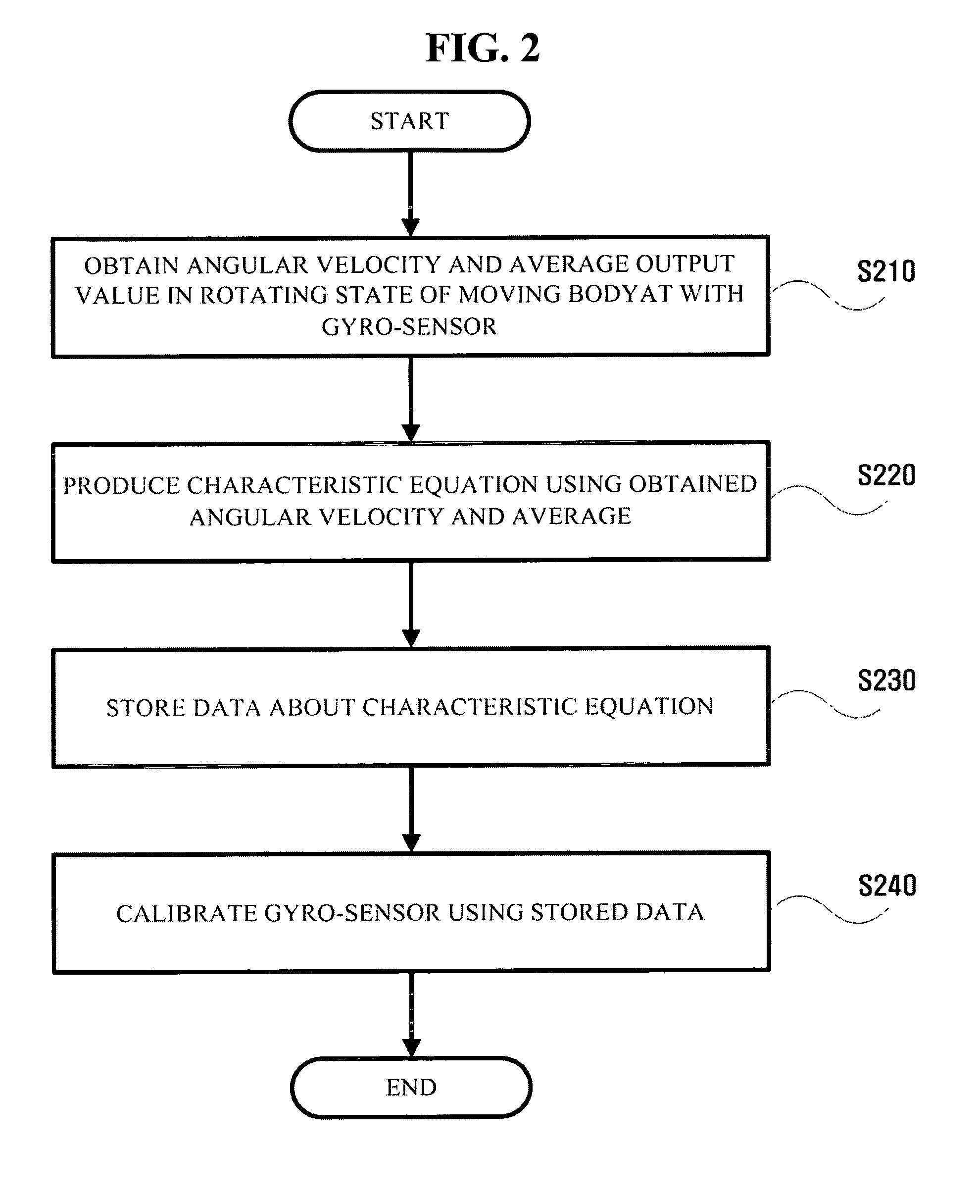
The present invention provides a method and apparatus for calibrating a gyro-sensor using data obtained by measuring an angular velocity and a gyro output value of a moving body equipped with the gyro-sensor. This allows for accurate location estimation of a mobile robot even when the temperature changes. The method includes measuring the angular velocity and the average output value of the gyro-sensor when the moving body rotates, obtaining data about the characteristic equation of the gyro sensor using the measured angular velocity and the average output value, and calibrating the gyro-sensor using the stored data about the characteristic equation. The apparatus includes a measurement module, an operation module, a storage module, and a calibration module. The invention enhances the efficiency of location estimation of a mobile robot and ensures accuracy in location estimation even at different temperatures.

Problems solved by technology

While ensuring excellent performance, high-priced gyro-sensors tend to be expensive and, as such, are not cost-effective when applied to mobile robots requiring cost competitiveness, e.g., robot vacuum cleaners.
However, calibrating each of a considerable number of gyro-sensors may involve an increase in the manufacturing cost, which is not cost-effective.
In addition, since the gyro-sensors and circuits characteristics may vary due to environmental factors changing with time, the accuracy of the gyro-sensors is likely to degrade after an extended use of period, which is generally called aging.
However, an offset of the gyro-sensor can be compensated for only in a stop mode and a characteristic curve based on a gyro characteristic equation cannot be calibrated.

Method used


Image

  • Method and apparatus for calibrating gyro-sensor
  • Method and apparatus for calibrating gyro-sensor
  • Method and apparatus for calibrating gyro-sensor

Examples


Embodiment Construction

[0025]Reference will now be made in detail to embodiments of the present invention, examples of which are illustrated in the accompanying drawings, wherein like reference numerals refer to the like elements throughout. The embodiments are described below in order to explain the present invention by referring to the figures.

[0026]A method and apparatus for calibrating a gyro-sensor according to an embodiment of the invention will be described with reference to the accompanying drawings.

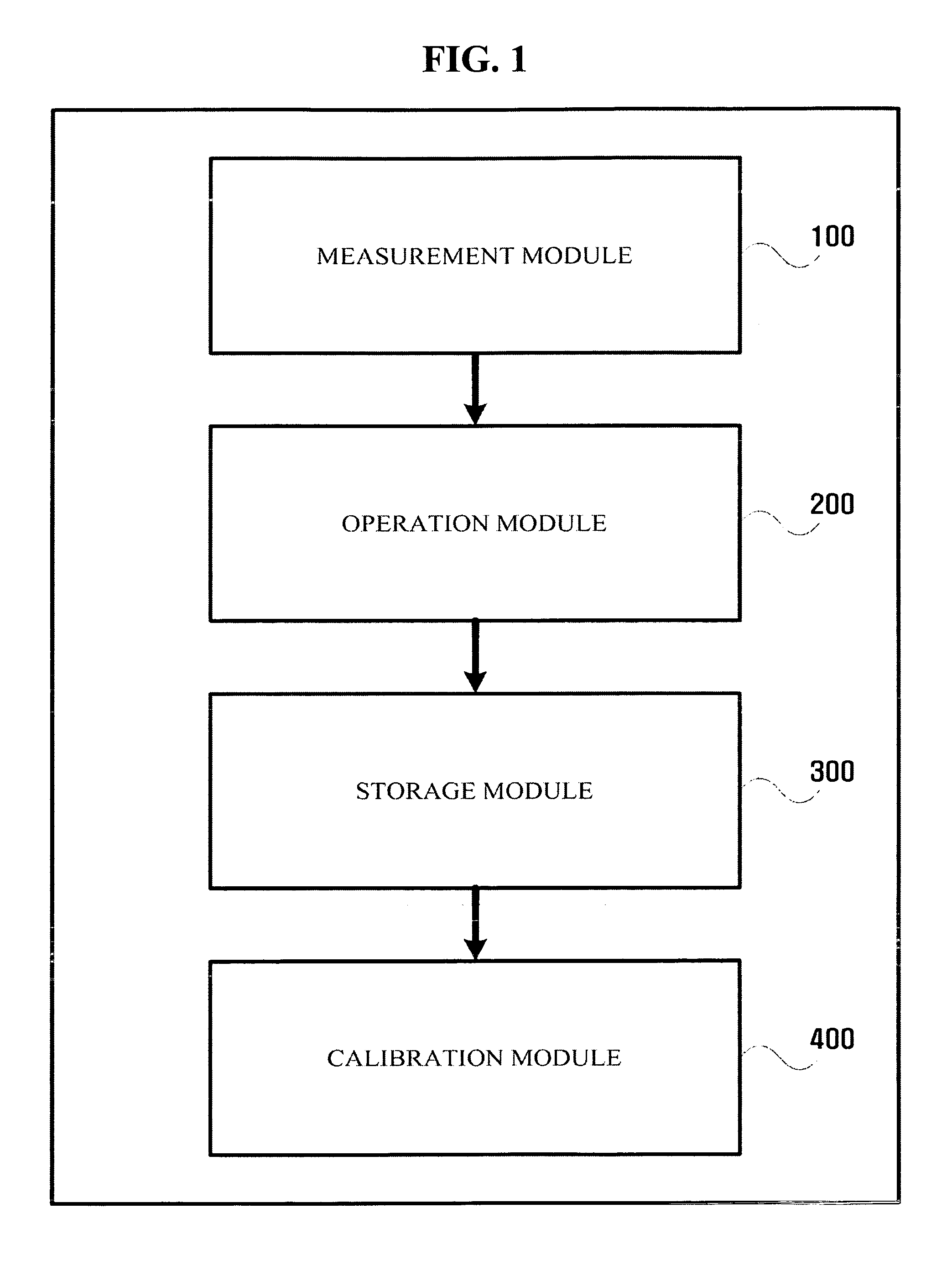
[0027]FIG. 1 is a block diagram of a gyro-sensor according to an embodiment of the present invention. Referring to FIG. 1, the gyro-sensor includes a measurement module 100 which measures an angular velocity and a gyro output value, an operation module 200 which obtains data about a characteristic curve, a storage module 300 which stores the data about the characteristic curve, and a calibration module 400 which calibrates the gyro-sensor.

[0028]To obtain a characteristic equation of an n-th degree repr...


PUM


Abstract

A method and apparatus for calibrating a gyro-sensor, by which a gyro-sensor can be calibrated using data which is obtained by measuring an angular velocity and a gyro output value of a moving body equipped with the gyro-sensor. The method includes measuring an angular velocity of a moving body and an average output value of the gyro-sensor when the moving body, equipped with the gyro-sensor, rotates, obtaining data about a characteristic equation of the gyro sensor using the measured angular velocity and the average output value and storing the data, and calibrating the gyro-sensor using the stored data about the characteristic equation.

Description

CROSS-REFERENCE TO RELATED APPLICATIONS[0001]This application is based on and claims priority from Korean Patent Application Nos. 10-2005-0087746 and 10-2006-0075221, respectively filed on Sep. 21, 2005 and Aug. 9, 2006, respectively, the disclosures of which are hereby incorporated herein by reference.BACKGROUND OF THE INVENTION[0002]1. Field of the Invention[0003]The present invention relates to a method and apparatus for calibrating a gyro-sensor, and more particularly, to a method and apparatus for calibrating a gyro-sensor by which a gyro-sensor can be calibrated using data which is obtained by measuring an angular velocity and a gyro output value of a moving body equipped with the gyro-sensor.[0004]2. Description of Related Art[0005]A gyro-sensor is one example of an inertial sensor. An inertial sensor senses the motion of a handheld terminal and may be configured with an accelerometer and a gyroscope. An accelerometer is a sensor that measures an acceleration of a moving obje...

Claims


Application Information

Patent Timeline
Patent Type & Authority Applications(United States)
IPC IPC(8): G01C25/00G01C21/10G01C19/00G01P21/02
CPCG01C25/00G01C19/00
Inventor CHOI, KI-WANLEE, HYOUNG-KIMYEONG, HYEONLEE, YONG-BEOM
Owner SAMSUNG ELECTRONICS CO LTD
Learn More