Floor Treatment Apparatus

a floor treatment and apparatus technology, applied in the field of floor treatment apparatus, can solve the problems of minimal lifting capacity and volume of the lifter, and achieve the effects of reducing lifting capacity, facilitating maneuverability, and facilitating the treatment of more of the floor surfa

Inactive Publication Date: 2009-04-16
KARCHER NORTH AMERICA INC
View PDF19 Cites 35 Cited by
  • Summary
  • Abstract
  • Description
  • Claims
  • Application Information

AI Technical Summary

Benefits of technology

[0018]It is one aspect of the present invention to provide a floor treatment apparatus that is easy to maneuver. More specifically, one embodiment of the present invention is constructed of a chassis section that includes an enclosure that houses at least a portion of the internal components of the treatment device and a location for installation of devices that are used during cleaning operations. In addition, one embodiment of the present invention provides a standing, leaning or sitting location for the operator. Another embodiment of the present invention is equipped with a powered steering device that allows for greater maneuverability in areas with tight corners, thereby ensuring that more of the flooring surface is treated without having to perform pre or post treatment operations. More specifically, one embodiment of the present invention is equipped with a self-propelled wheel and an easy to use steering device to provide increased maneuverability around obstacles. One embodiment of the present invention employs at least one wheel that provides thrust and / or steering capability. Yet another embodiment of the present invention employs wheels that are substantially centered under the chassis such that the entire apparatus is generally capable of 360° rotation without substantially traversing in any other direction, thus allowing it to treat tight corners of a surface. It is another aspect of the present invention to provide a cleaning apparatus that is cost effective to manufacture. Various aspects of the invention shall now be described in more detail.Chassis

Problems solved by technology

In addition, especially in older buildings that have been retrofitted to comply with the Americans with Disabilities Act, elevators are of minimal volume and lifting capability.

Method used


Image

  • Floor Treatment Apparatus
  • Floor Treatment Apparatus
  • Floor Treatment Apparatus

Examples


Embodiment Construction

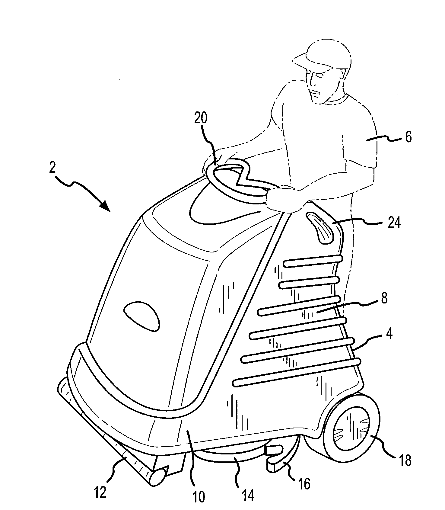
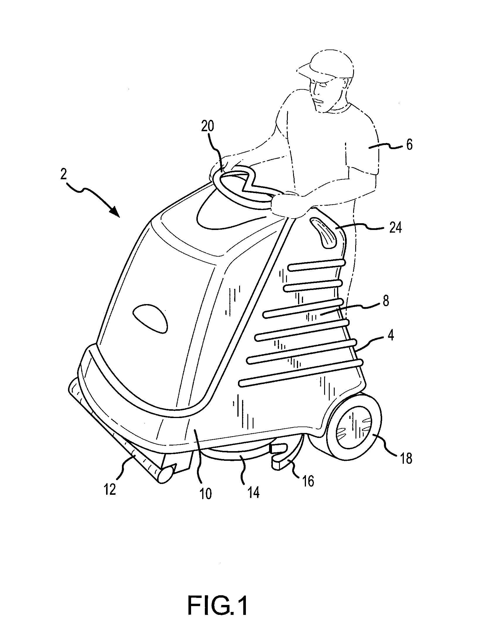
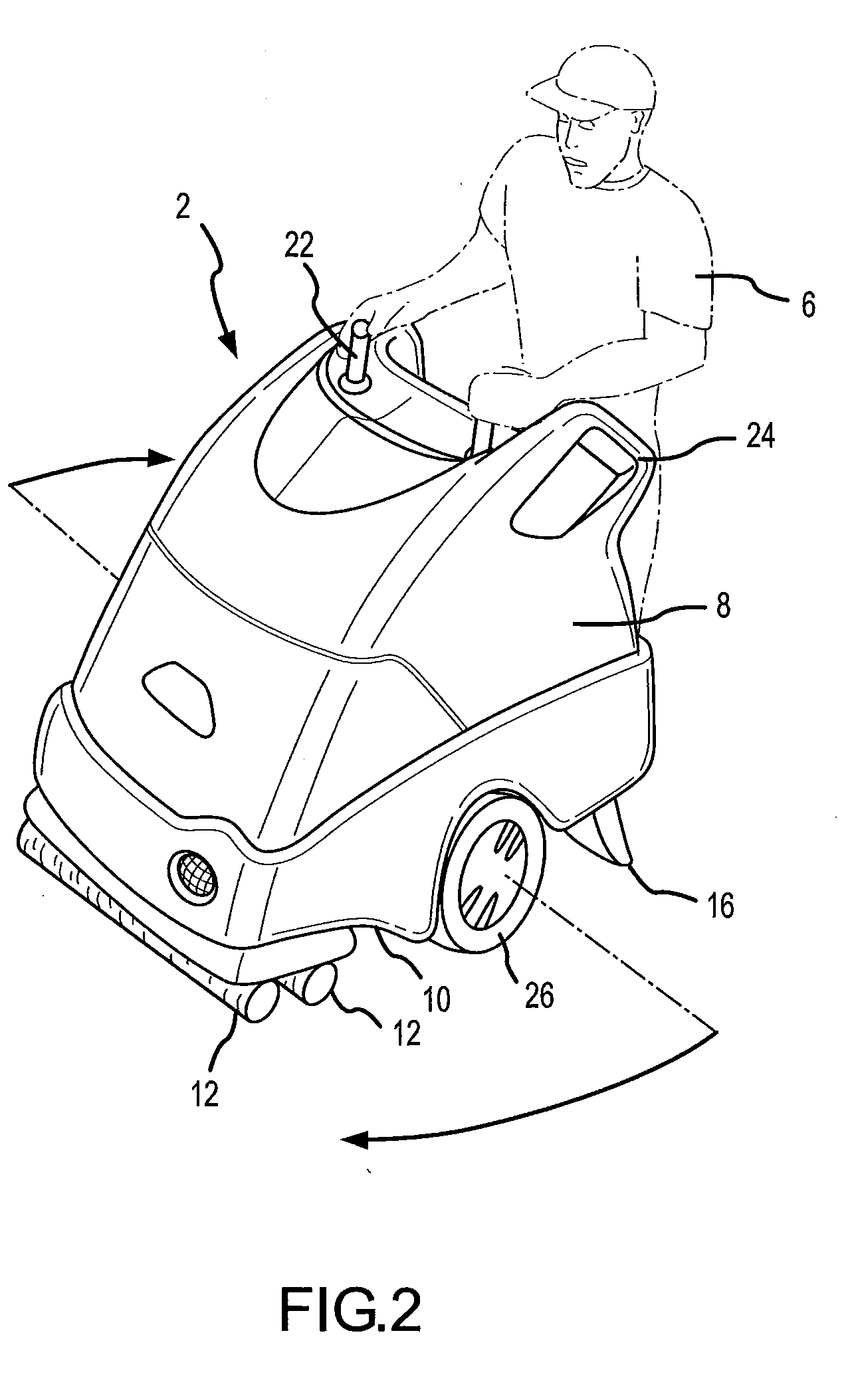
[0072]Referring now to FIGS. 1-20 an apparatus 2 for cleaning or otherwise treating a floor surface is shown. More specifically, one embodiment of the present invention includes a chassis 8 with a platform 4 that is adapted to support the weight of an operator 6, thus increasing the efficiency of the entire floor treatment operation. In addition, various cleaning or floor treatment components may be interconnected to the bottom surface 10 of the chassis, such as brushes 12, scrubbers 14, squeegees 16, vacuum shoes, etc.

[0073]The chassis 8 also includes a plurality of wheels 18 operably interconnected to the bottom surface 10 to enable steering and provide stability. It is contemplated that the operator 6 will stand on the platform 4 and steer the apparatus 2 with either a steering wheel 20 or other type of steering mechanism, such as a joy stick 22. Such an embodiment of the present invention enables the floor surface to be cleaned or otherwise treated more efficiently, since the op...


PUM


Abstract

The present invention relates generally to an apparatus for cleaning or otherwise treating a floored surface that includes a platform adapted to support the weight of an operator. In addition, one embodiment of the present invention is capable of generally performing 360° turns to facilitate the treatment of difficult to access portions of the floored surface.

Description

[0001]This application is a Continuation of U.S. patent Ser. No. 11 / 059,663, filed Feb. 15, 2005, which claims the benefit of U.S. Provisional Patent Application Serial Nos. 60 / 545,153 and 60 / 627,606, filed Feb. 16, 2004 and Nov. 12, 2004, respectively, and which is a Continuation-In-Part of U.S. patent application Ser. No. 10 / 737,027, filed Dec. 15, 2003, which is a Continuation-In-Part of U.S. patent application Ser. No. 10 / 438,485, filed May 14, 2003, the entire disclosures of which are incorporated by reference in their entirety herein.[0002]This application is related to U.S. patent application Ser. No. 11 / 253,100, filed Oct. 17, 2005, which is incorporated by reference in its entirety herein.FIELD OF THE INVENTION[0003]The present invention relates to an apparatus for the treatment, such as cleaning, of a surface. More specifically, one embodiment of the present invention is an apparatus for surface cleaning that provides a standing or sitting location for the operator and is ...

Claims


Application Information

Patent Timeline
Patent Type & Authority Applications(United States)
IPC IPC(8): A47L11/00A47L5/00A47L11/02B08B3/02
CPCB08B3/026A47L11/4066B08B2203/027B08B2203/0217B60L3/00B60L7/24B60L15/2018B60L2200/40B60L2240/12B60L2270/142B60L2270/145Y02T10/72B60L50/66Y02T10/64Y02T10/70A47L11/145A47L11/03A47L11/16A47L11/20A47L11/292A47L11/302A47L11/24A47L11/4044A47L11/4061A47L11/305A47L11/34A47L11/4016A47L11/4038A47L11/4041A47L11/4083A47L11/4088
Inventor PEDLAR, ROGERDOLL, BRIAN J.SIMMON, RUSTYGREEN, NEVINPEARSON, DANIELTRAN, LOI X.GORSKY, ROBERT S.SHARK, ERIC L.VENARD, DANIEL C.
Owner KARCHER NORTH AMERICA INC
Why Eureka
Try Eureka