Method of replacing supporting bearing for rolling roll

a technology of supporting bearing and rolling roll, which is applied in the direction of roller bearings, mechanical equipment, manufacturing tools, etc., can solve the problems of reducing the life of the supporting bearing for supporting the rolling roll, requiring an enormous replacement cost at a time, and serious influence on the rolling operation, so as to reduce the replacement cost, increase the rating load of the new supporting bearing, and smoothly perform the transition

Inactive Publication Date: 2009-04-16
JTEKT CORP
View PDF20 Cites 3 Cited by
  • Summary
  • Abstract
  • Description
  • Claims
  • Application Information

AI Technical Summary

Benefits of technology

[0008]The invention has been made in view of the above described circumstances, and it is an object of the invention to provide a method of replacing a supporting bearing for a rolling roll in which replacing cost which would be required at a time can be reduced, and a period for stopping operation of a rolling mill can be shortened to the least, by enabling the supporting bearing to be replaced in steps for a new supporting bearing having an increased rating load.

Problems solved by technology

However, there occurs a problem that life of a supporting bearing for supporting the rolling roll is decreased due to such increase of the rolling load and the rolling speed.
In this case, serious influence is given to the rolling operation.
However, in order to replace the supporting bearings in the entire rolling mill at a time, new supporting bearings corresponding to the number of the rolling rolls must be prepared in advance, which requires an enormous replacing cost at a time.
There is another problem that operation of the rolling mill must be stopped for a long time to conduct replacing works.
In this case, it takes more time to conduct the replacing works, and the operation of the rolling mill must be stopped for a longer time.

Method used


Image

  • Method of replacing supporting bearing for rolling roll
  • Method of replacing supporting bearing for rolling roll
  • Method of replacing supporting bearing for rolling roll

Examples


Embodiment Construction

[0025]Now, an embodiment of the invention will be described referring to the drawings.

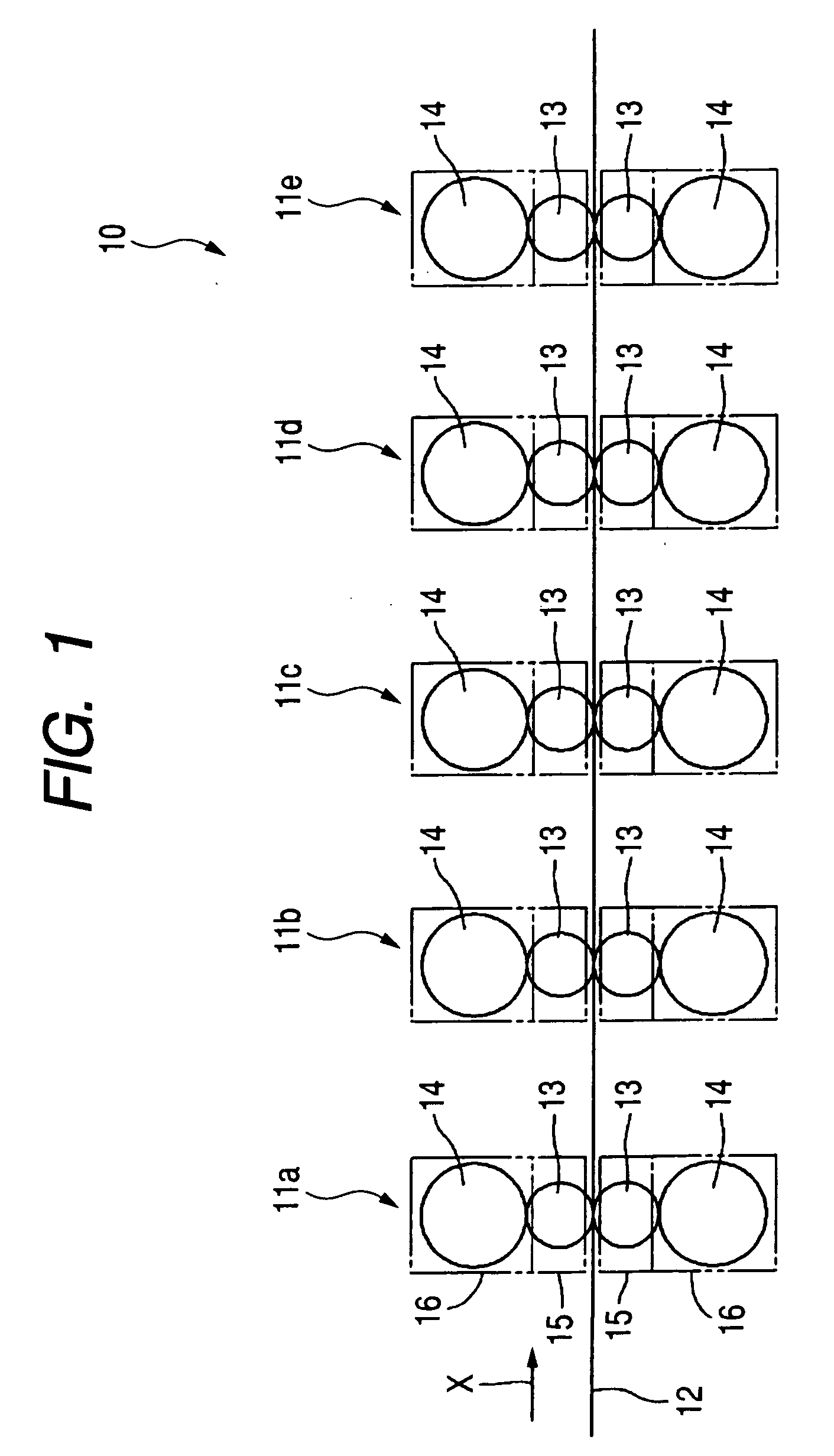
[0026]FIG. 1 is a schematic view of a tandem rolling mill 10 to which the invention can be applied.

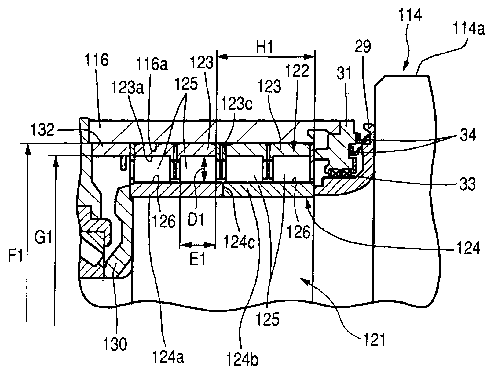
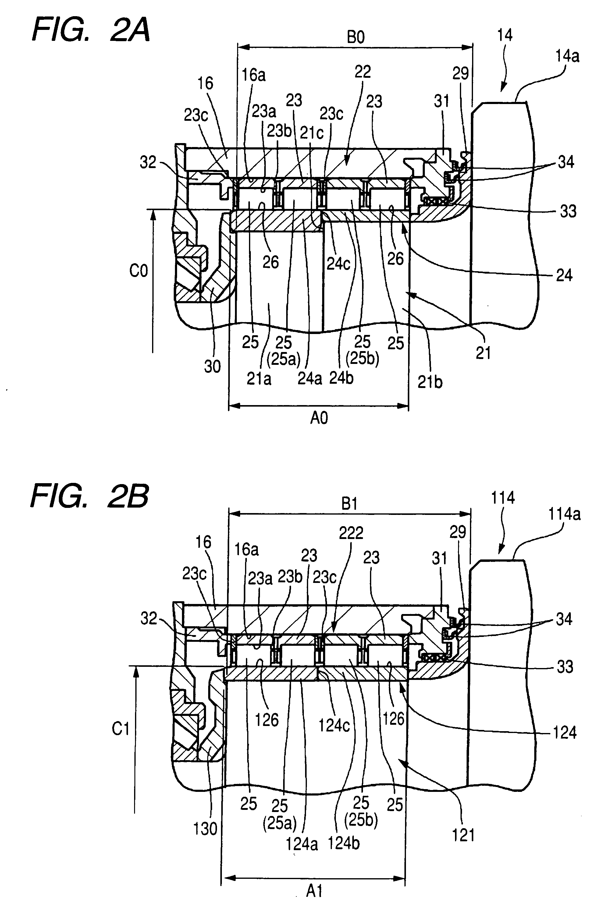
[0027]This tandem rolling mill 10 includes a plurality of rolling stands (first to fifth stands) 11a to 11e which are provided at intervals in a direction X in which material to be rolled 12 flows. Each of the rolling stands 11a to 11e is, for example, a four step rolling mill, and provided with rolling rolls including a pair of upper and lower work rolls 13 and a pair of upper and lower backup rolls 14. The rolls 13, 14 are respectively supported by roll chocks 15, 16 each having supporting bearings incorporated at both ends thereof in an axial direction.

[0028]The method of replacing the supporting bearing according to this invention can be applied to either or both of the work roll 13 and the backup roll 14. However, in the following description, particularly, the case where the invention is applied...


PUM

PropertyMeasurementUnit
diameteraaaaaaaaaa
axial lengthaaaaaaaaaa
outer diameteraaaaaaaaaa

Abstract

A supporting bearing is replaced with a new supporting bearing by conducting a first step and a second step. In the first step., an old inner ring before replacement is replaced with a new inner ring having an inner ring raceway diameter same as the old inner ring, and an axial length of an inner ring raceway face longer than the old inner ring so that a rolling roll is supported by this new inner ring in combination with an old outer ring and old cylindrical rollers. Thereafter, in the second step, the old cylindrical rollers are replaced with new cylindrical rollers having an axial length longer than the old cylindrical rollers, and simultaneously, the old outer ring is replaced with a new outer ring having an axial length of an outer ring raceway face longer than the old outer ring.

Description

BACKGROUND OF THE INVENTION[0001]1. Field of the Invention[0002]The present invention relates to a method of replacing a supporting bearing for a rolling roll, and more particularly, to the method of replacing the supporting bearing with a new supporting bearing having an increased rating load.[0003]2. Related Art[0004]In recent years, production facilities, particularly, operation rate of a rolling mill tends to be increased along with expansion of demands for steel products. Because of this increase of the operation rate, it has been conducted to increase rolling load and rolling speed.[0005]However, there occurs a problem that life of a supporting bearing for supporting the rolling roll is decreased due to such increase of the rolling load and the rolling speed. For example, data show that in the supporting bearing for supporting backup rolls in a four step rolling mill, when the rolling load is increased by 10%, the life is decreased by 27%, when the rolling speed is increased b...

Claims


Application Information

Patent Timeline
Patent Type & Authority Applications(United States)
IPC IPC(8): B23P6/00
CPCB21B31/07F16C13/02F16C19/28Y10T29/49721Y10T29/49698Y10T29/4973Y10T29/49696Y10T29/49545Y10T29/49638F16C2322/12
Inventor KUBO, JUNICHISUZUKI, NOBUYA
Owner JTEKT CORP
Why Eureka
Try Eureka