Sock

a technology for socks and soles, applied in the field of socks, can solve the problems of no escape route, inability to introduce air from the outside of the shoe to the inside of the shoe, etc., and achieve the effects of increasing air permeability, high water absorption ability, and rapid drying properties

Inactive Publication Date: 2009-04-16
OKAMOTO INDS
View PDF10 Cites 58 Cited by
  • Summary
  • Abstract
  • Description
  • Claims
  • Application Information

AI Technical Summary

Benefits of technology

[0003]Socks are commercially available which employ materials with a high degree of water absorbability and rapid drying properties, as well as materials with a mesh structure, aiming to produce a sock with an internal environment as comfortable to the wearer as possible.
[0004]Heretofore, there has also been disclosed a sock with a plain knitted portion and a pile knitted portion disposed in a lattice configuration in the arch portion of the sock, with increased air permeability at specified areas of the sole portion.
[0005]However, due to the fact that the temperature of the entire sole rises during walking, there is the problem that the sock of Japanese Laid-Open Patent Application No. 2001-295104, which increases air permeability only in the arch portion, an area of the sole which does not touch the ground, cannot increase air permeability as fully as expected, simply because humid air is trapped inside the shoe.
[0006]A sock is disclosed in Japanese Utility Model Registration No. 3113253 in which a sock has a knitted structure with mesh knitting at the base portions of toes on the instep side and the sole side, and in the arch portion, and with pile knitting in the sole portion and the toe portion. However, the sock of Japanese Utility Model Registration No. 3113253 had improved air permeability primarily only at the base portions of toes and in the arch portion, which are areas of the sole which do not touch the ground. Therefore, there is the problem that sufficient ventilation cannot be achieved, even with the alternating mesh knitting and pile knitting being additionally disposed on the front of the ankle and on the instep portion, due to the fact that no provision was made for air to escape from the sock or from the shoe.
[0007]In Japanese Utility Model Registration No. 3121397 given below, there is disclosed a sock with a band with uneven configuration formed by varying the pile lengths provided at a uniform width on the outer surface of the sole portion, and with a plurality of uneven bands formed on the front side of the arch portion across the entire circumference of the foot from the sole to the instep.
[0008]However, in the case of the above-described sock of Japanese Utility Model Registration No. 3121397, there is also the problem that sufficient ventilation cannot be achieved, since no provision was made for humid air to escape from the sock or from the shoe. The steamy feeling is not eliminated, even if an uneven band is formed along the entire circumference of the foot from the sole to the instep, since the humid air circulates along this uneven band.

Problems solved by technology

The problems to be solved are that, in the prior art sock, air permeability is improved only at certain positions on the sock, that no escape route for air is provided for humid air to escape from the shoe, and that it is impossible to introduce air from the outside of the shoe to the inside of the sock to increase ventilation.

Method used


Image

  • Sock
  • Sock
  • Sock

Examples


examples

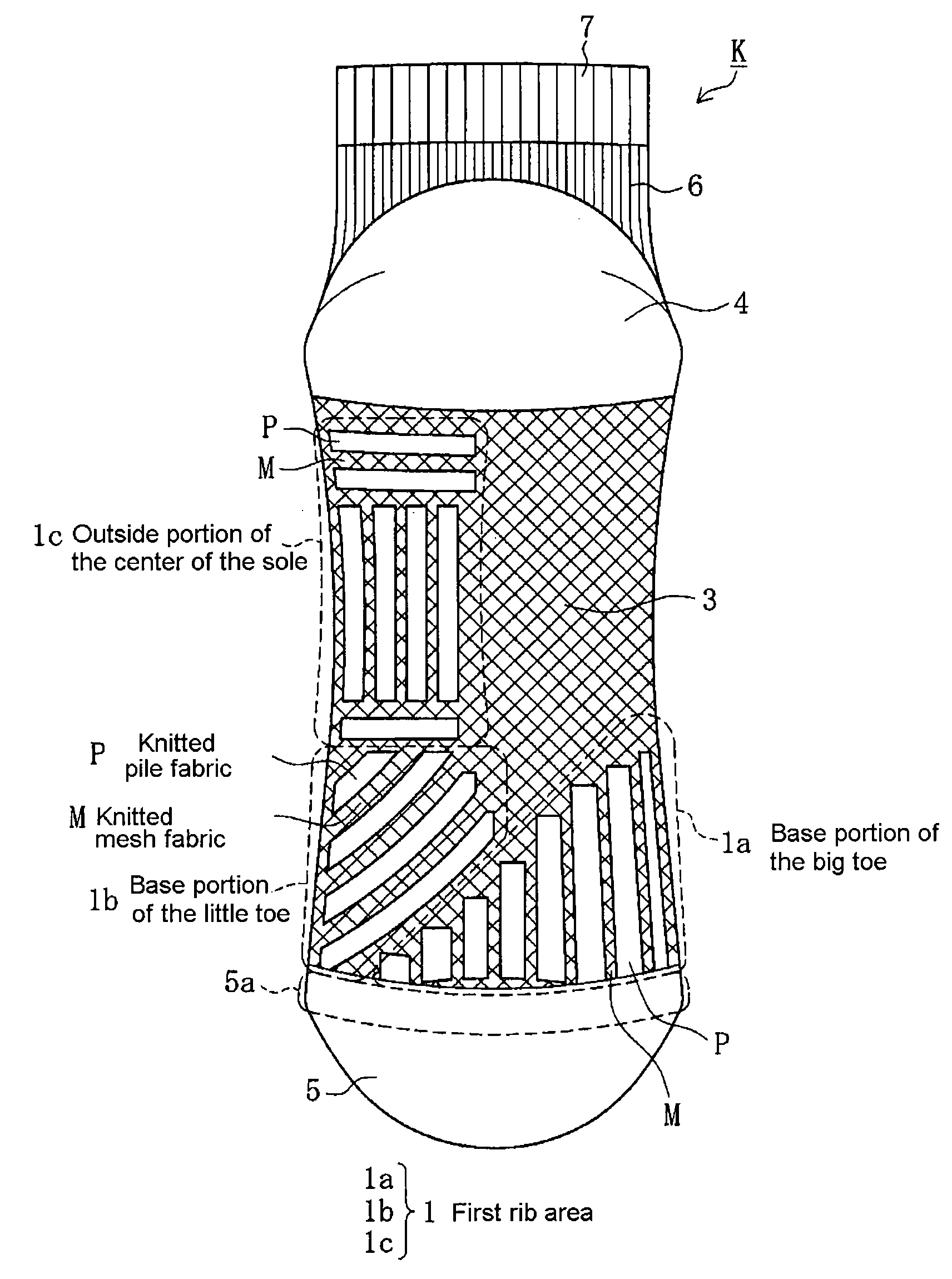
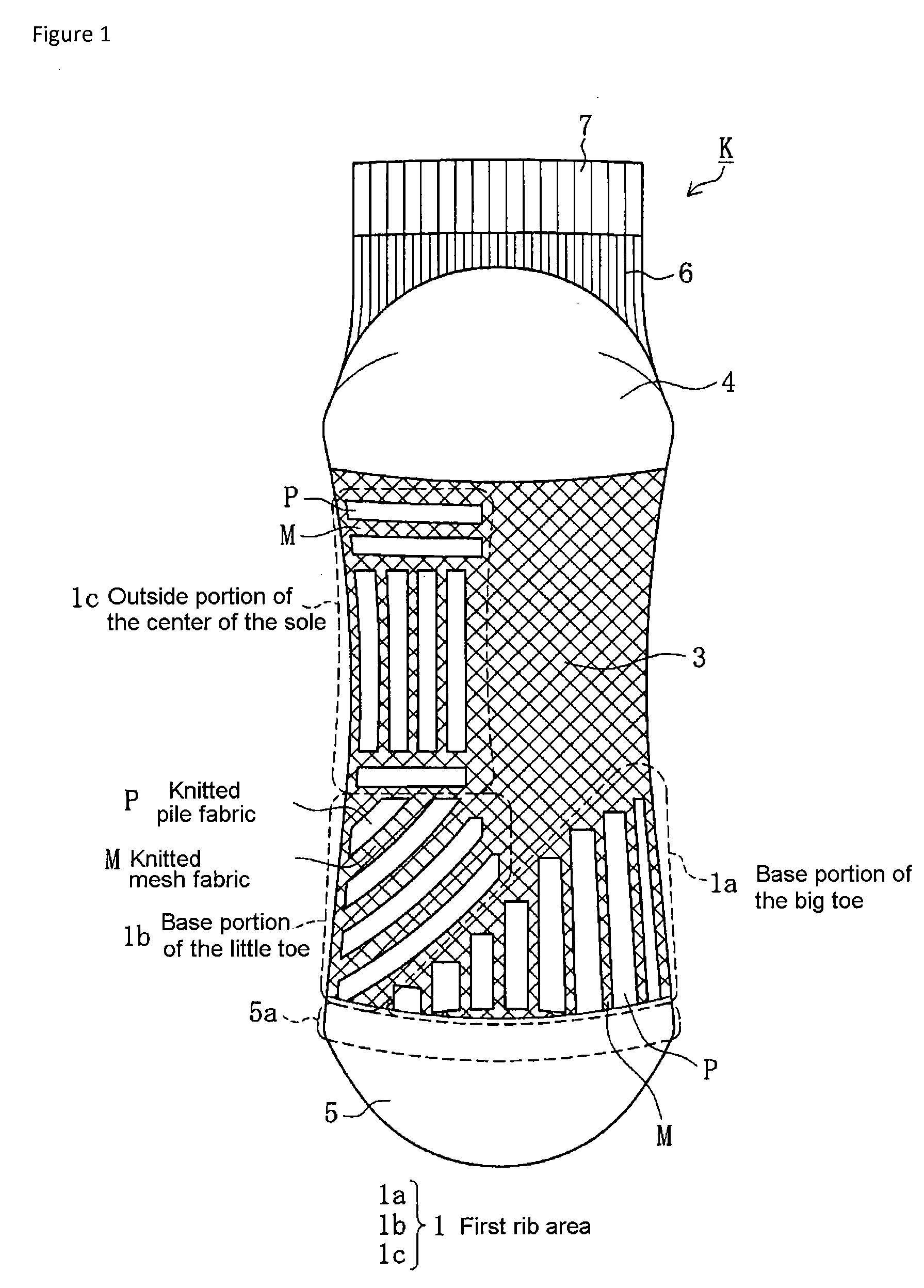
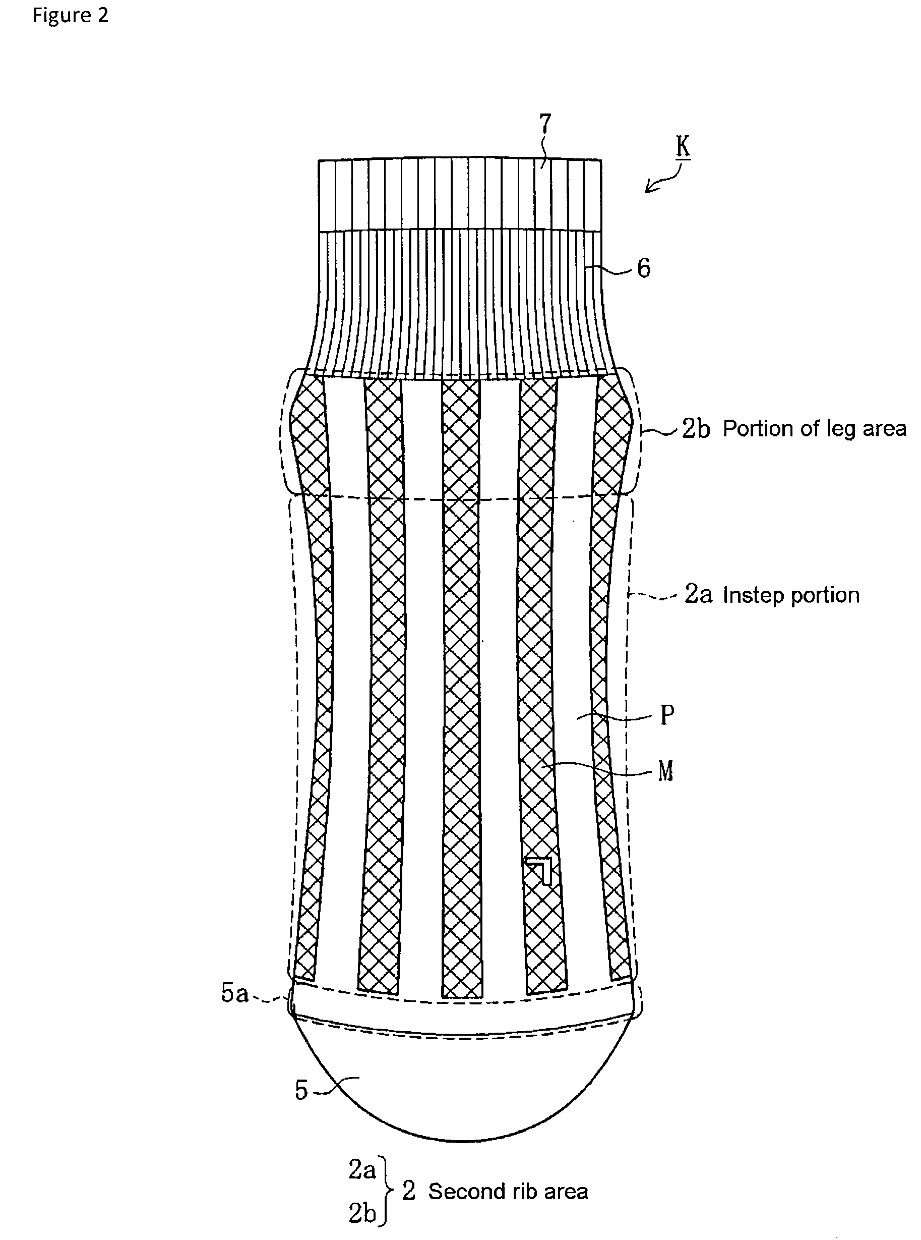
[0039]The sock of the present invention is described in further detail with examples below. FIG. 1 is a drawing illustrating a sock of the present invention for use on the left foot, as viewed from the plane of the sole portion. FIG. 2 is a drawing illustrating the sock of FIG. 1 as viewed from the plane of the instep portion. FIG. 3 is a drawing illustrating the sock of FIG. 1 as viewed from the plane of the big toe. FIG. 4 is a drawing illustrating the sock of FIG. 1 as viewed from the plane of the little toe.

[0040]Sock K of this example uses a cotton / polyester blend (60% cotton / 40% polyester) with a high degree of water absorbability and rapid drying properties. An ordinary knitting machine is used to knit with front yarns and back yarns. FTY, which has good knitting properties, is used for the back yarns. FTY is a fiber commonly used as a back yarn in socks, with nylon fibers or polyester fibers covering polyurethane fibers.

[0041]As shown in FIGS. 1-4, the sock K of this example...


PUM


Abstract

A sock includes an air escape route that allows humid air to be expelled to the outside of a shoe. The sock may include a first rib area provided in a ground-touching area of a sole portion of the sock, the ribs being formed in a desired direction. A second rib area, in which ribs are formed in a wale direction, may also be provided in an instep portion of the sock. The ribs of the first and second rib areas may be knitted with alternating knitted pile and knitted mesh fabric. Humid air collecting in areas that do not touch the ground passes through the concave portions of the ribs of the first rib area, and is impelled toward the instep side. Air flowing to the instep side of the sock via the first rib area is expelled to the outside of the shoe via the second rib area.

Description

RELATED APPLICATIONS[0001]This application claims priority under 35 U.S.C. §119 to Japanese Patent Application No. JP2007-264871 filed Oct. 10, 2007, the entire content of which is hereby incorporated by reference.TECHNICAL FIELD[0002]The present invention relates to a sock having the advantageous effects of greater functionality in the ventilation of air inside and outside of the sock, as well as suppressing increases in temperature and humidity within the sock to the greatest extent possible.BACKGROUND ART[0003]Socks are commercially available which employ materials with a high degree of water absorbability and rapid drying properties, as well as materials with a mesh structure, aiming to produce a sock with an internal environment as comfortable to the wearer as possible.[0004]Heretofore, there has also been disclosed a sock with a plain knitted portion and a pile knitted portion disposed in a lattice configuration in the arch portion of the sock, with increased air permeability ...

Claims


Application Information

Patent Timeline
Patent Type & Authority Applications(United States)
IPC IPC(8): D04B9/46A43B17/00
CPCA41B11/02A41B2400/60D04B1/104D04B1/26D04B1/02
Inventor ARAKI, TAKAHIROWATATANI, CHIKA
Owner OKAMOTO INDS
Why Eureka
Try Eureka