Support system for solar energy generator panels

a solar energy generator and support system technology, applied in the direction of heat collector mounting/support, light and heating equipment, sustainable buildings, etc., can solve the problems of large roof area that cannot be used for solar power generation, large deployment of such systems, and permanent fixtures

Inactive Publication Date: 2009-04-16
BARNES CHRISTOPHER
View PDF34 Cites 35 Cited by
  • Summary
  • Abstract
  • Description
  • Claims
  • Application Information

AI Technical Summary

Problems solved by technology

However, several drawbacks to solar power have prevented widespread deployment of such systems 100.
Such drilling can require adherence to building codes, hiring of contractors to do the work, and other expenses on top of the cost of the solar power system 100 itself.
Generally, no panels are placed within “dead zones,” detrimentally effect overall current generation and

Method used


Image

  • Support system for solar energy generator panels
  • Support system for solar energy generator panels
  • Support system for solar energy generator panels

Examples


Embodiment Construction

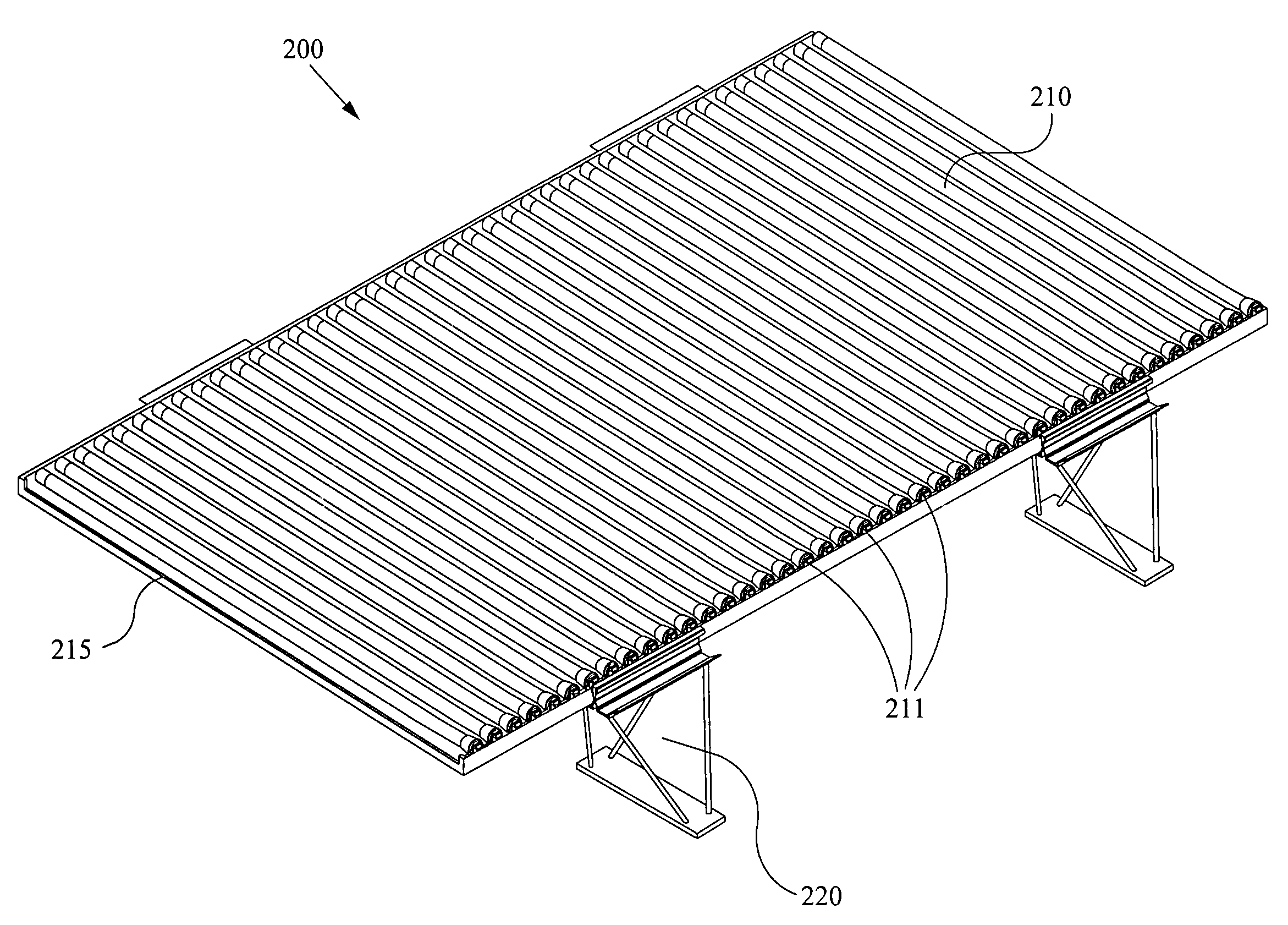
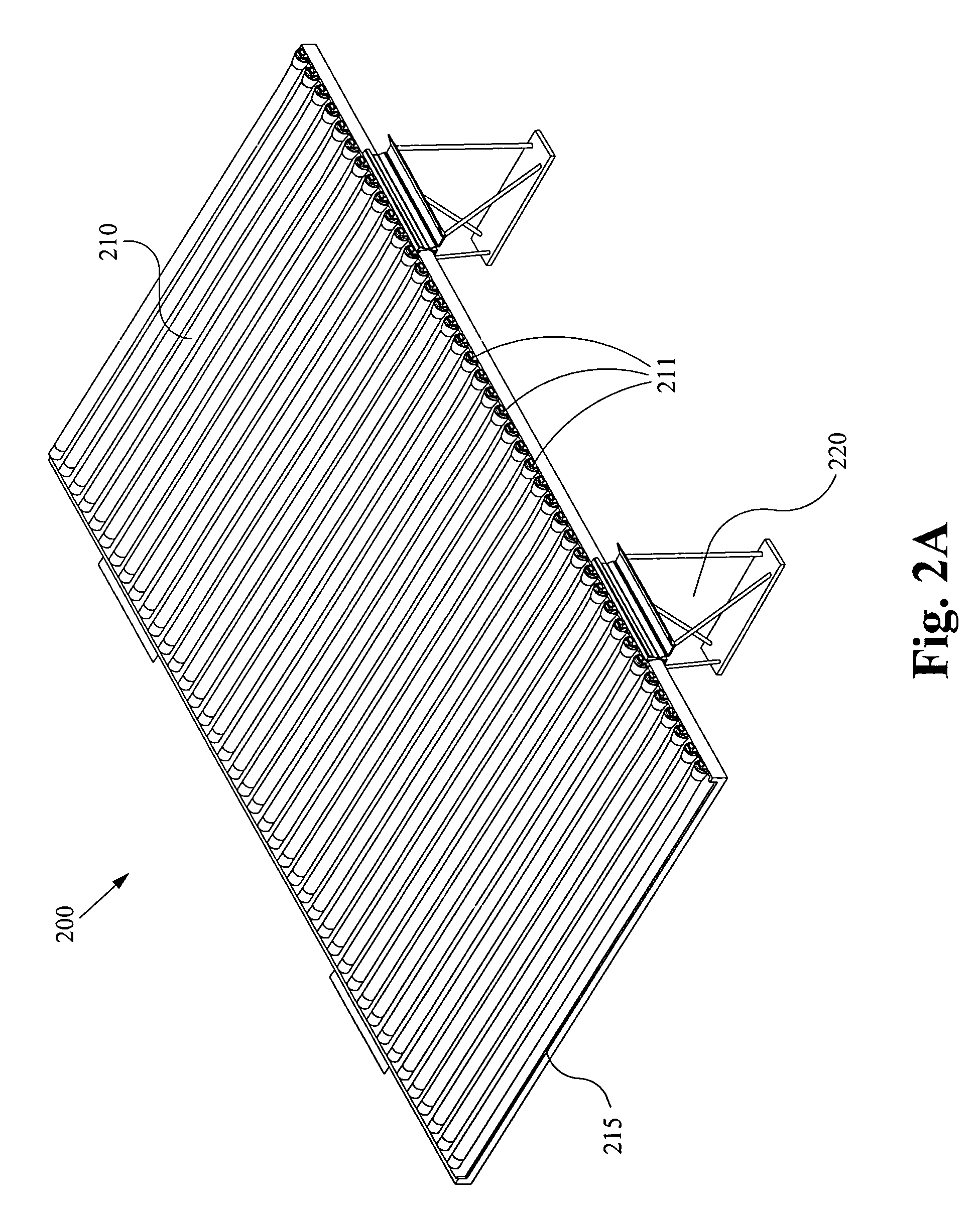
[0011]Methods and apparatuses directed to supports and systems for supporting solar panels are described herein. In general, supports and support systems for flat lying solar panels are envisioned. In this specification and claims, the term “support” can refer to an object for holding a solar panel above a surface. Furthermore, “solar panel” can refer to a planar solar cell, collection of solar cells, a frame holding at least one planar or non-planar solar cell, or the like. Other embodiments of the present invention will readily suggest themselves to people skilled in the relevant arts. Other embodiments, although time consuming to discover, would nonetheless be a routine engineering effort to such skilled people having the benefit of this disclosure.

[0012]Reference will now be made in detail to implementations of the present invention as illustrated in the accompanying drawings. The drawings may not be to scale. The same reference indicators will be used throughout the drawings an...


PUM


Abstract

A support system for a solar panel comprises a plurality of legs configured to receive multiple solar panels. The legs each comprise a base, a plurality of shafts, and a support precipice. The support precipice is divided into two sides by a t-bar. The first side comprises a guiding wing to effectuate modular assembly of the support system. The second side comprises a beveled edge to effectuate secure coupling of a solar panel. The system is able to be assembled and disassembled without the use of tools or implements. The system is also movable.

Description

FIELD OF THE INVENTION [0001]The present invention is related to mounting apparatus for solar panels. More specifically, the present invention is related to modular support systems for solar panels.BACKGROUND OF THE INVENTION [0002]Current trends in energy production point towards a need for both renewable resources and “green” resources. As the actual, environmental and political costs of fossil fuels continue to rise and accelerate, consumers demand alternate energy sources that are quickly deployable and easily plug and play into existing energy providing networks. To that end, solar power has become a prevalent source for both residential and commercial buildings. FIG. 1 shows a typical solar power system 100 in current practice. Generally, solar cells 110 are angled south when utilized in the Northern hemisphere. The specific angle is usually determined as a function of latitude, to maximize incident sunlight 120 with the solar cell 110. However, several drawbacks to solar powe...

Claims


Application Information

Patent Timeline
IPC IPC(8): F24J2/46
CPCF24J2/5232F24J2/5239F24J2002/0038H01L31/035281H02S20/00Y02B10/20Y02E10/47Y02E10/50F24J2/5245Y02B10/12H02S20/24F24S25/16F24S25/12F24S2020/10F24S25/61Y02B10/10
Inventor BULLER, BENYAMINGRONET, CHRISTRUMAN, KELLYBREZOCZKY, THOMAS
Owner BARNES CHRISTOPHER
Why Eureka
Try Eureka