

Fiber Placement Machine Platform System Having Interchangeable Head and Creel Assemblies
a technology of fiber placement machine and platform system, which is applied in the direction of document inserter, transportation and packaging, other domestic articles, etc., can solve the problem that the tool on which the composite material is laid is often quite complex
- Summary
- Abstract
- Description
- Claims
- Application Information
AI Technical Summary
Problems solved by technology
Method used
Image

Examples
Embodiment Construction
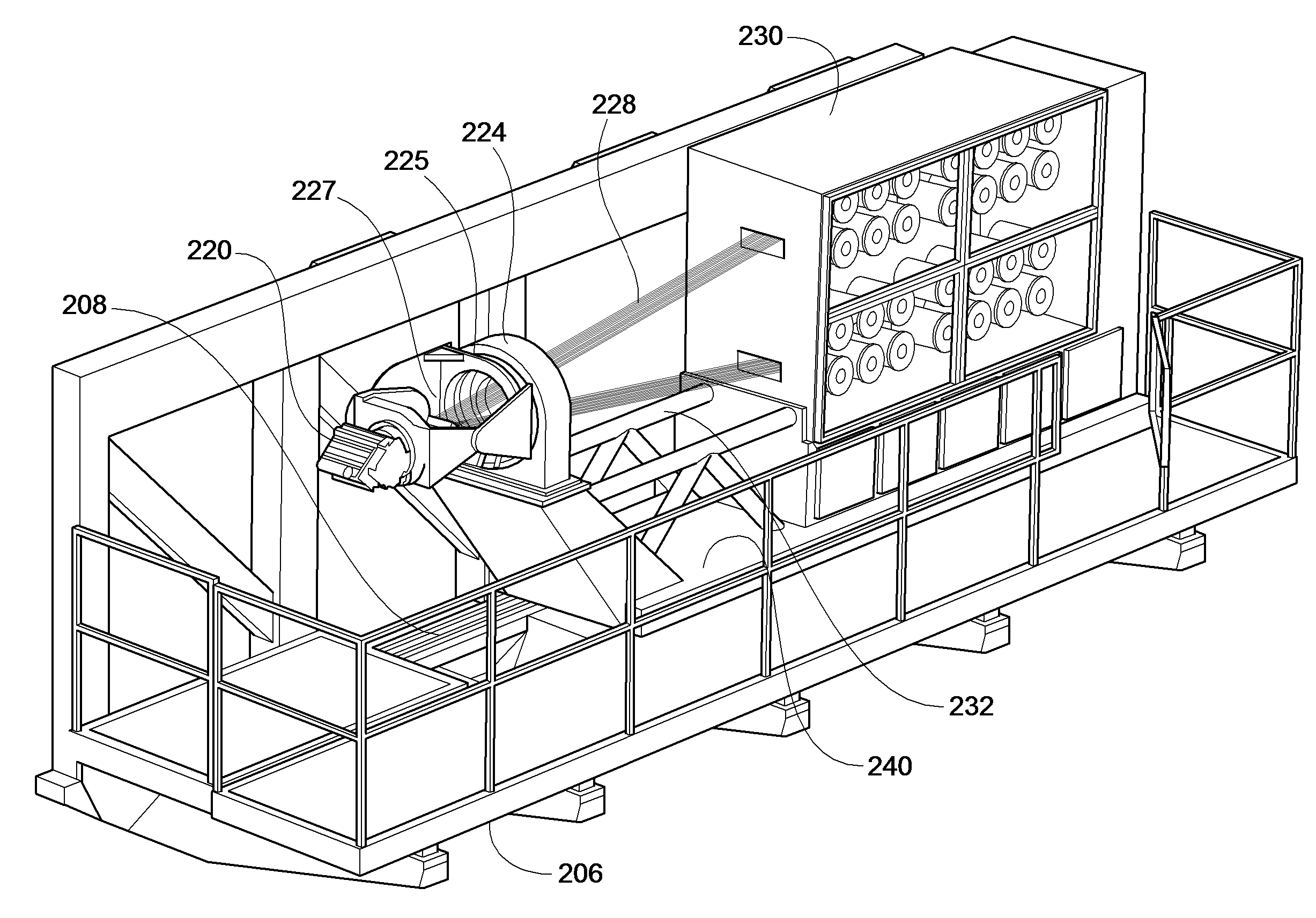
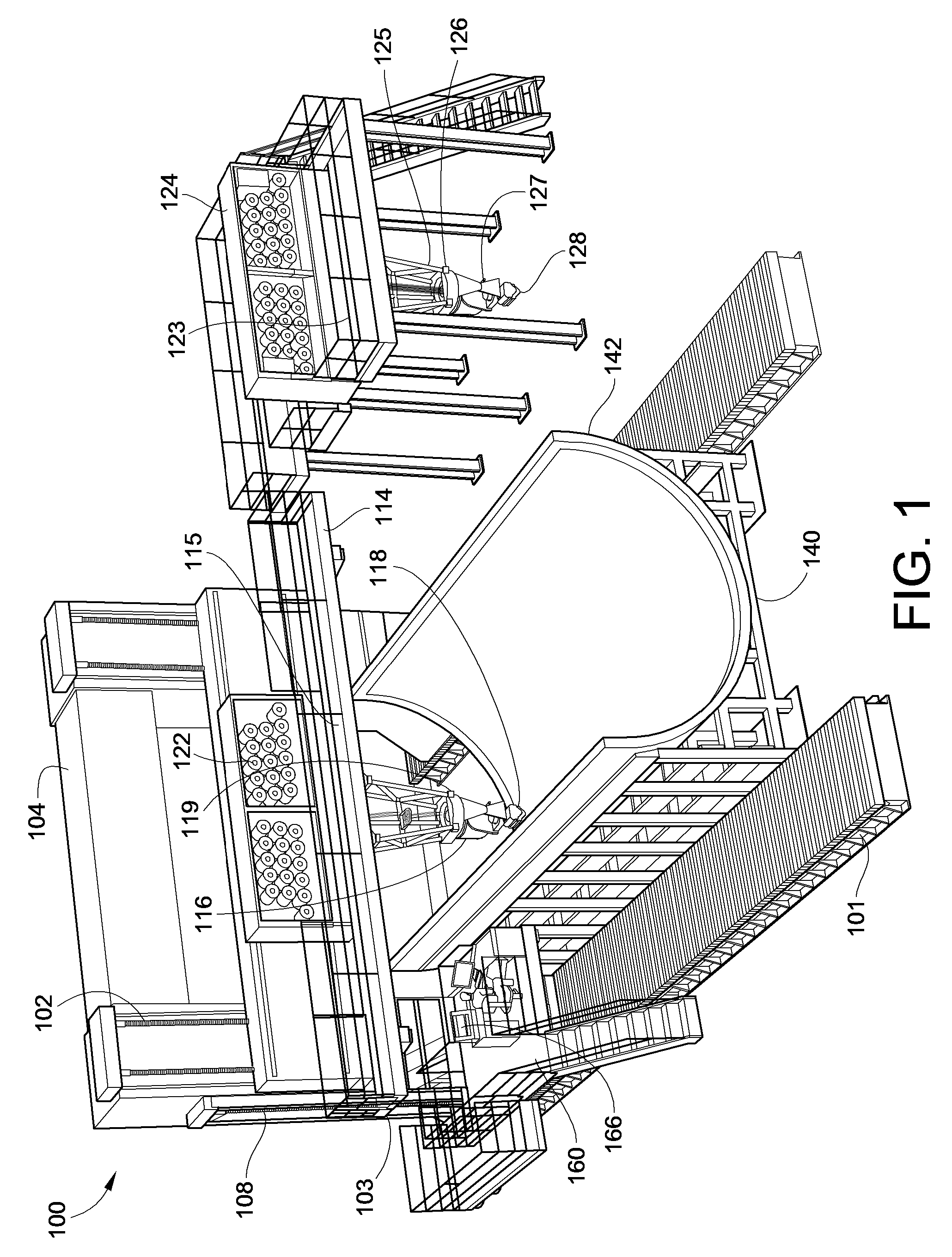
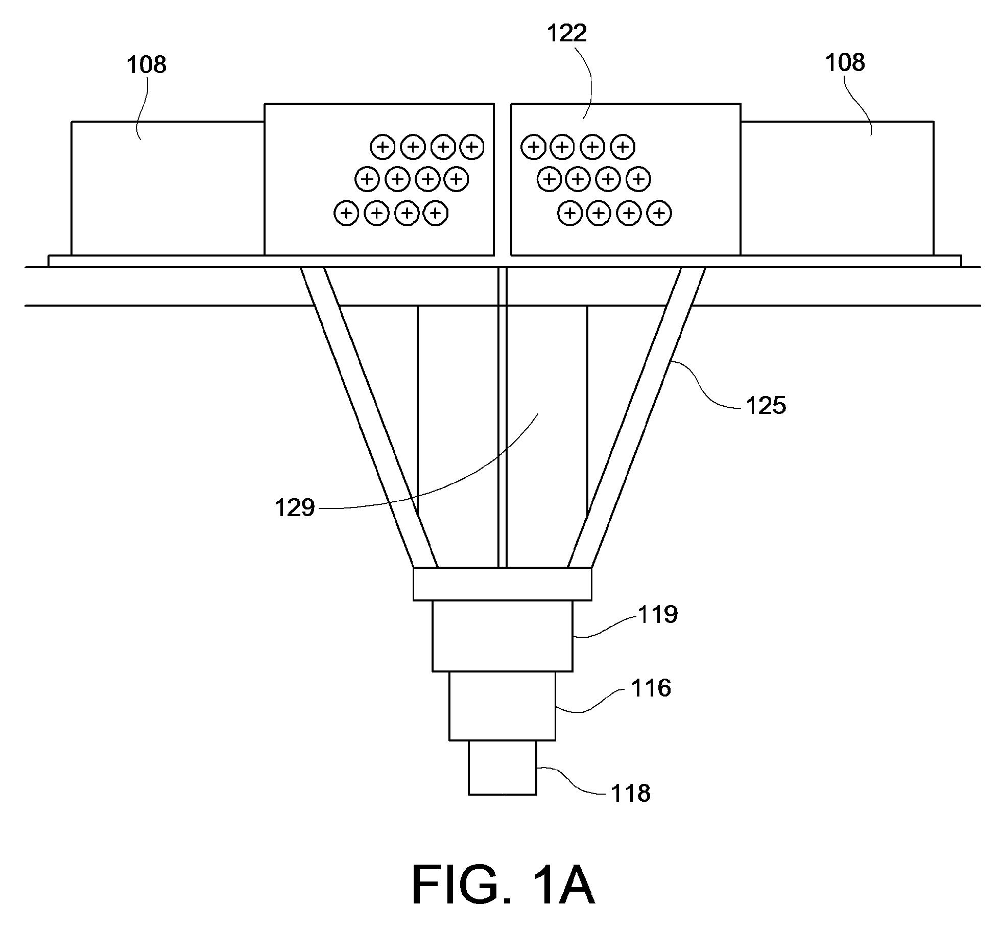
[0025]In an embodiment of the invention, a fiber placement machine 100, which includes a compact fiber placement head 118 and a support structure 125 therefor, having one or more internal motors 119 for positioning the fiber placement head 118 is used. The internal motors 119 may be constructed with a hollow core for passage therethrough of multiple tows 123 of material. Use of internal motors 119 in accordance with the invention, allows the manipulation of the pivot axis mechanism 116 of the multi-axial fiber placement head 118 and support structures 125 therefor to be smaller than prior heads and support structures in which the head 118 was positioned by motors driving through mechanical drive trains, having gears, pulleys, chains, etc. Use of the internal motor driven redirect mechanism also provides for significantly faster positioning and repositioning of the fiber placement head 118, than was achievable with prior drive arrangements.
[0026]Further, as shown in FIG. 1, the fiber...
PUM
| Property | Measurement | Unit |
|---|---|---|
| distance | aaaaa | aaaaa |
| time | aaaaa | aaaaa |
| angle | aaaaa | aaaaa |
Abstract
Description
Claims
Application Information