Electromagnetic exciter and manufacturing method therefor

a technology of electromagnetic exciter and manufacturing method, which is applied in the field of electromagnetic exciter, can solve the problems of increasing the height of the electromagnetic exciter, unsuitable for inability to meet the requirements of a reduction in thickness, so as to facilitate the assembly of parts and facilitate the positioning of the stator. , the effect of reducing the number of components

Inactive Publication Date: 2009-04-16
CITIZEN ELECTRONICS CO LTD
View PDF6 Cites 68 Cited by
  • Summary
  • Abstract
  • Description
  • Claims
  • Application Information

AI Technical Summary

Benefits of technology

[0024]The method may be carried out as follows. In the unfolded casing body blank forming step, the unfolded casing body blank is formed with a pair of strip portions extending from the opposite ends, respectively, of an outer peripheral edge portion of the unfolded casing body blank that is to form one of the side wall portions of the casing body. The pair of strip portions are serpentined inwardly to form a pair of resilient support members. In the oscillator-disposing step, the distal end portions of the pair of resilient support members are fixed to the opposite ends, respectively, of the oscillator to support the oscillator. By so doing, the number of component parts is reduced, and the assembly of the parts is facilitated.
[0025]The method may be carried out as follows. In the unfolded casing body blank forming step, first through-holes for positioning the stator are formed in a portion of the unfolded casing body blank that is to form the bottom wall portion of the casing body. In the casing body forming step, pins are fitted and secured into the through-holes, respectively. In the stator-disposing step, the pins are fitted into through-holes for positioning provided in the stator to position the stator relative to the bottom wall portion of the casing body. In the casing forming step, the pins are fitted into second through-holes for positioning the stator, and the pins are provided in the cover, to secure the stator between the casing body and the cover. The use of pins facilitates the positioning of the stator. Even if an impact is applied to the electromagnetic exciter during use due, for example, to a fall, the stator can be prevented from being displaced. Thus, the reliability of the electromagnetic exciter can be increased.
[0026]The method may be carried out as follows. In the unfolded casing body blank forming step, a plurality of snap-engaging portions are formed in portions of the unfolded casing body blank that are to form the side wall portions of the casing body. In the casing forming step, the snap-engaging portions are engaged with snap-engaging portions formed on the side wall portions of the cover to secure the casing body and the cover to each other. By so doing, the mounting of the cover is facilitated.
[0027]The oscillator may have a permanent magnet, a magnetic member and a weight of a high specific gravity material disposed on a single support plate in close contact with each other in a plane to form a plate-shaped structure as a whole. With this arrangement, the oscillator can be reduced in thickness, and it is possible to form a magnetic circuit having a reduced reluctance.
[0028]The arrangement may be as follows. The yoke has a bar shape. The coil has a first coil portion wound around an end portion of the yoke at one side of a central portion of the yoke and a second coil portion wound around an end portion of the yoke at the other side of the central portion. The yoke has magnetic pole portions at the central and end portions thereof. The magnetic pole portions at the end portions are arranged to generate the same magnetic pole. The magnetic pole portion at the central portion is arranged to generate a magnetic pole opposite in polarity to the magnetic pole generated in the magnetic pole portions at the end portions. The permanent magnet has a first permanent magnet and a second permanent magnet connected together in a straight line. The first and second permanent magnets face the first and second coil portions, respectively, substantially parallel thereto. The first and second permanent magnets have magnetic poles opposite in polarity to each other at their surfaces facing the first and second coil portions, respectively. In this case, the coil may be formed by winding a single wire, and the first and second coil portions may be opposite in winding direction but equal to each other in the number of turns of the wire. Because the two coil portions are formed by using a single wire, the making of the coil is facilitated, and the circuit for applying an alternating voltage can be simplified.

Problems solved by technology

A vibration-generating device having such a structure, however, has a circular cylindrical configuration as a whole and is therefore unsuitable for a reduction in thickness.
Further, because the eccentric weight is rotated to generate vibration, the rotating shaft is subjected to severe stress, which gives rise to problems in terms of durability and reliability.
Consequently, the height of the electromagnetic exciter increases, which hinders reduction in thickness of a mobile device into which the electromagnetic exciter is incorporated.

Method used


Image

  • Electromagnetic exciter and manufacturing method therefor
  • Electromagnetic exciter and manufacturing method therefor
  • Electromagnetic exciter and manufacturing method therefor

Examples


Embodiment Construction

[0071]Embodiments of the present invention will be explained below with reference to the accompanying drawings.

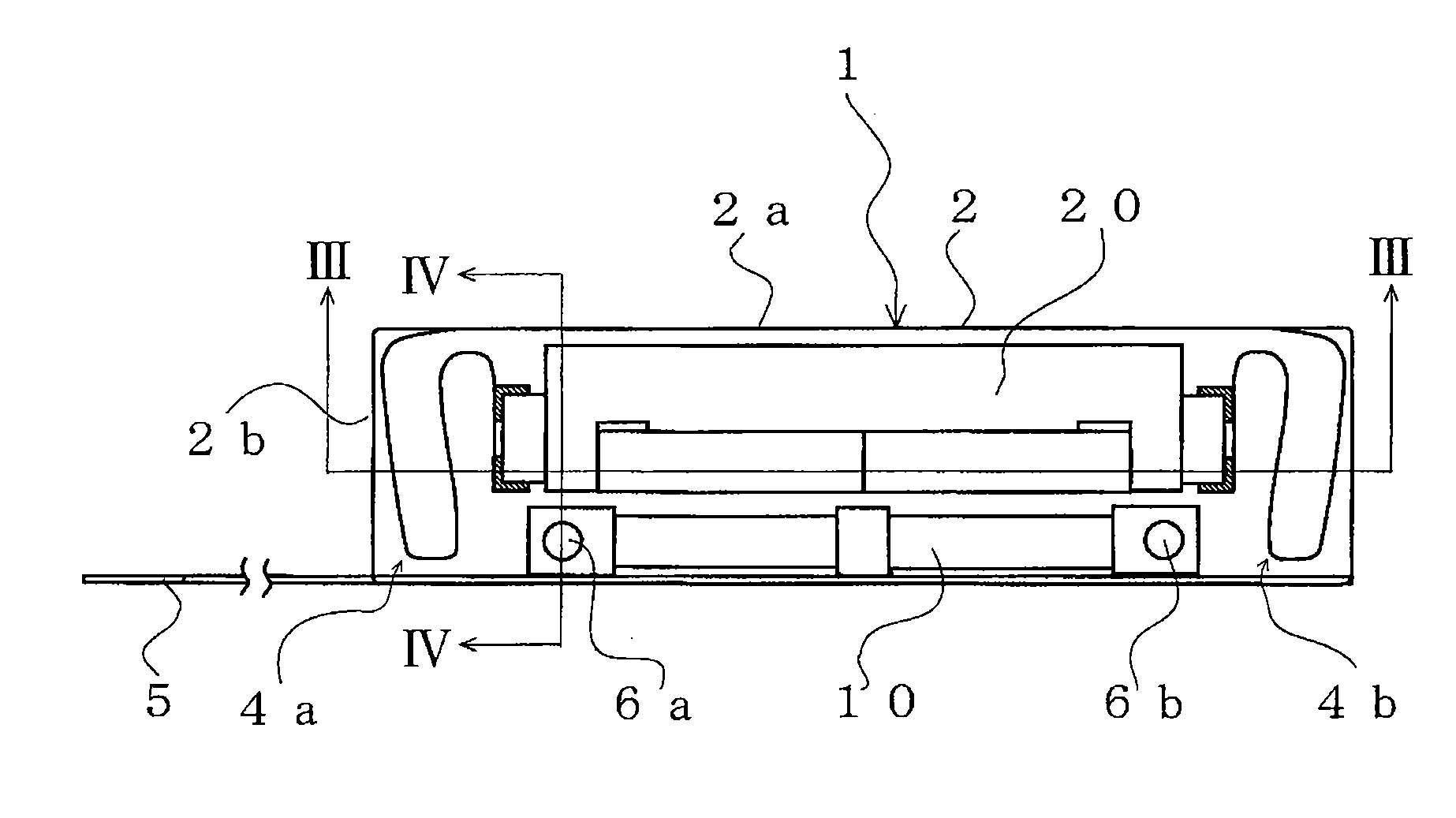
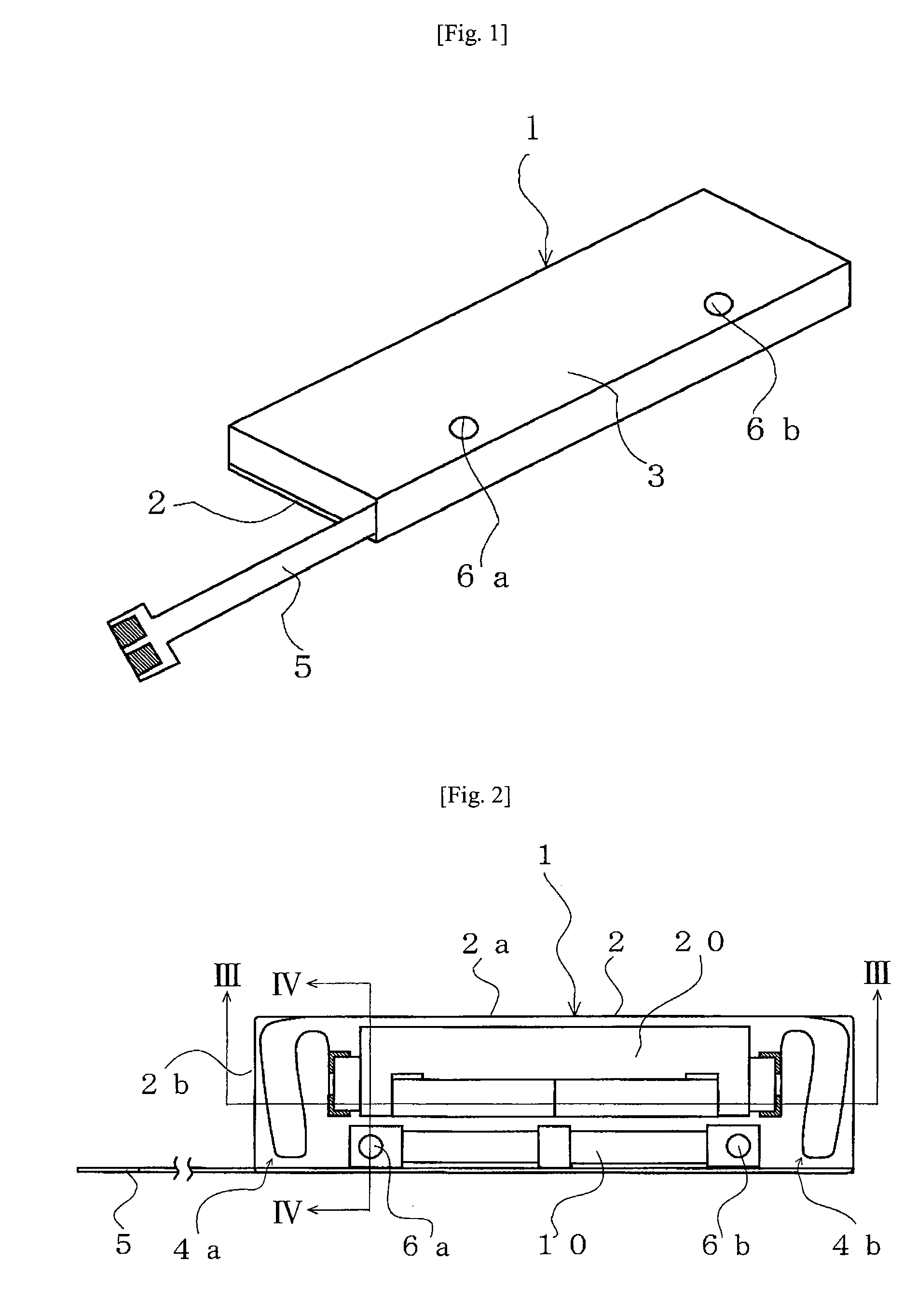
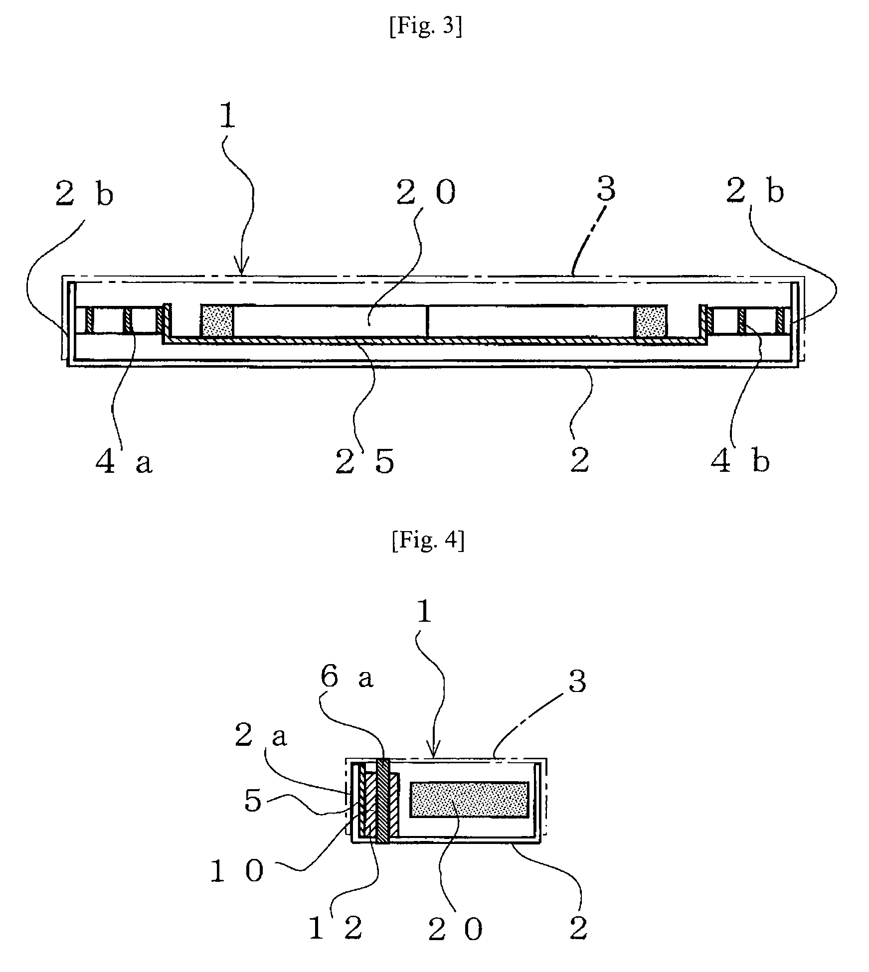
[0072]In FIG. 1, an electromagnetic exciter 1 according to a first embodiment of the present invention has an electromagnetic exciter main body (described later) housed in a flat casing comprising a casing body 2 and a cover 3 (see FIG. 18), which is described later. A flexible printed circuit board (FPC) 5 for connection with an external circuit is led out from one end of the electromagnetic exciter 1. It should be noted that the casing may be a substantially box-shaped casing having a substantially flat plate integrally formed therewith to close the top thereof.

[0073]FIG. 2 is a top plan view showing the electromagnetic exciter 1 in FIG. 1 with the cover 3 removed therefrom to allow the main body part of the electromagnetic exciter 1 to be seen. In the exciter 1, a stator 10 and an oscillator 20 are disposed adjacently in parallel to long-side wall portions 2a of a rectan...


PUM

PropertyMeasurementUnit
specific gravityaaaaaaaaaa

Abstract

A thin electromagnetic exciter has a flat casing including a casing body (2) and a cover (3), a stator (10) including an electromagnet having a coil wound around a yoke, and an oscillator (20) including a bar-shaped permanent magnet and a weight integrally attached thereto. The stator and the oscillator are disposed adjacently over a bottom wall portion (2c) of the casing body. The stator is secured to the casing body. The oscillator is vibratably supported relative to the casing body through resilient support members.

Description

[0001]This application claims priority under 35 U.S.C. §119 to Japanese Patent application Nos. JP2007-265085 filed on Oct. 11, 2007, JP2007-310249 filed on Nov. 30, 2007, JP2007-321243 filed on Dec. 12, 2007, JP2007-322025 filed on Dec. 13, 2007, JP2007-339914 filed on Dec. 28, 2007, and JP2008-011169 filed on Jan. 22, 2008, the entire contents of which are hereby incorporated by reference.TECHNICAL FIELD[0002]The present invention relates to an electromagnetic exciter that can be incorporated in thin mobile devices such as mobile phones. The present invention also relates to a method of manufacturing such an electromagnetic exciter.RELATED ART[0003]Thin mobile devices such as mobile phones each generally have a vibration-generating device, e.g. an electromagnetic exciter, to inform the user of an incoming call by a beep sound or, alternatively, by vibration in trains or at meetings where noises should not be made.[0004]Many of conventional vibration-generating devices have an ecce...

Claims


Application Information

Patent Timeline
Patent Type & Authority Applications(United States)
IPC IPC(8): H02K33/16H02K15/00
CPCY10T29/49009B06B1/045
Inventor OTA, YOSHIZUMIWATANABE, TAKAHISA
Owner CITIZEN ELECTRONICS CO LTD
Why Eureka
Try Eureka