Heat radiation structure for portable projector

Active Publication Date: 2009-04-16
SAMSUNG ELECTRONICS CO LTD
View PDF3 Cites 13 Cited by
  • Summary
  • Abstract
  • Description
  • Claims
  • Application Information

AI Technical Summary

Benefits of technology

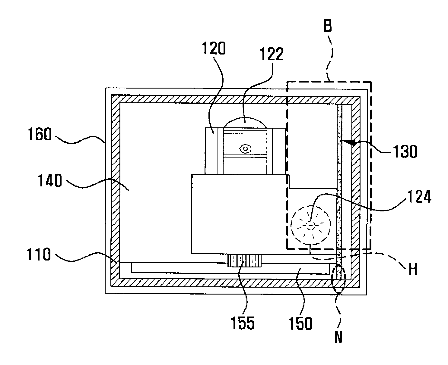
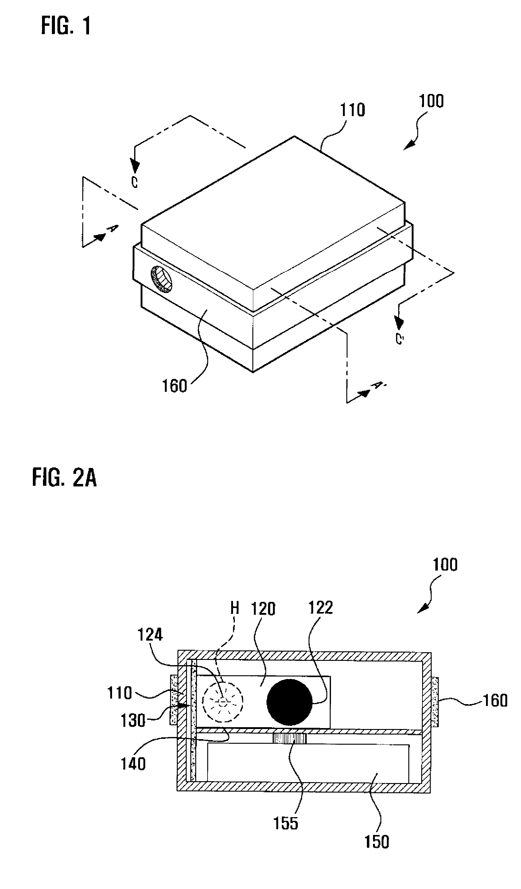
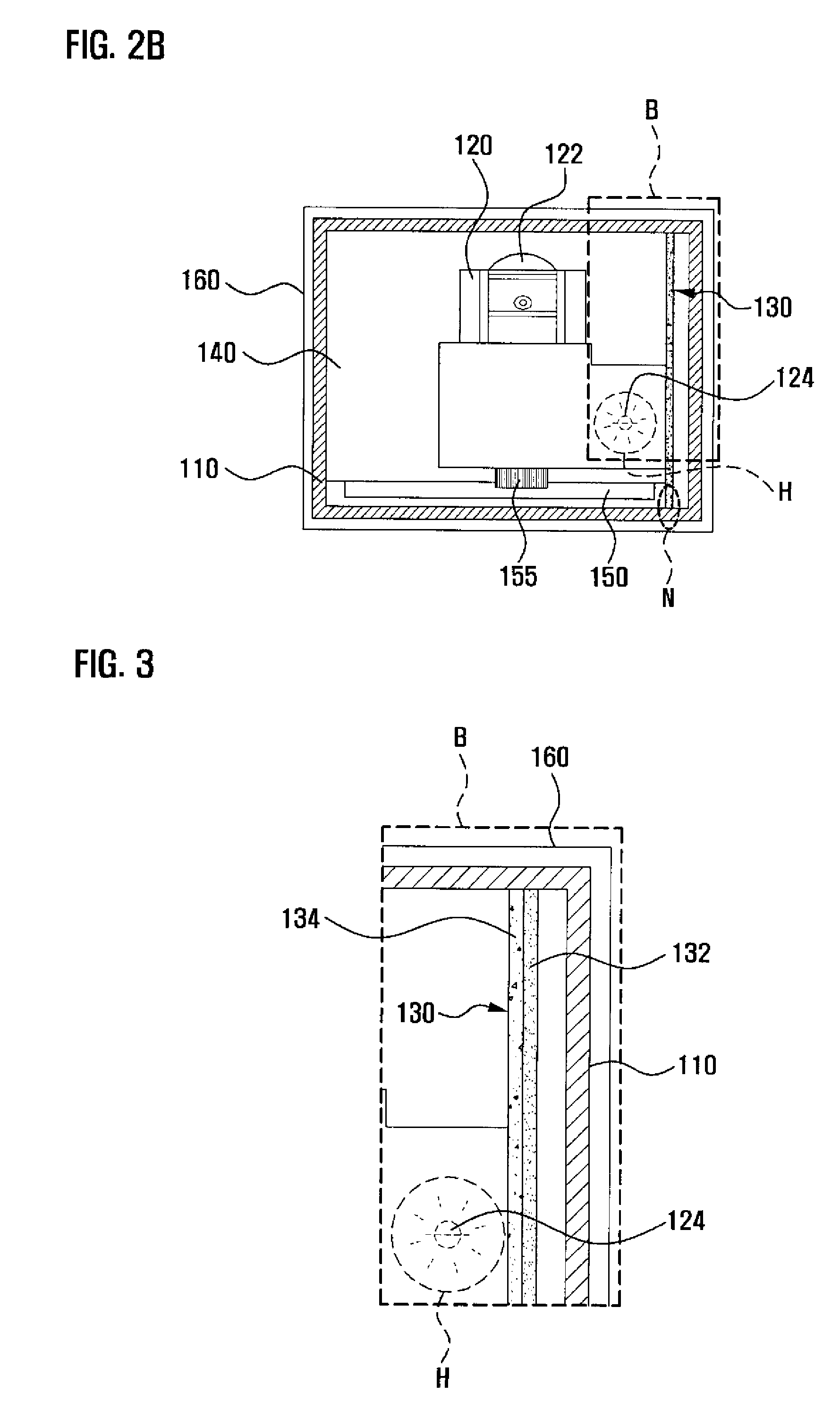
[0012]According to the present invention, a heat radiation structure for a portable projector efficiently transfers heat generated in a projector module to a heat radiation case using a thermally conductive plate. The heat transferred

Problems solved by technology

Accordingly, mobile communication terminals are becoming complex communication terminals and necessaries of modern people.
There is a degree of difficulty for such a micro projector (hereinafter, referred to as ‘portable projector’) to radiate heat generated therein.
In other words, the size of a portable projector is so small that the portab

Method used


Image

  • Heat radiation structure for portable projector
  • Heat radiation structure for portable projector
  • Heat radiation structure for portable projector

Examples


Embodiment Construction

[0022]Hereinafter, exemplary embodiments of the present invention will be described in detail with reference to the accompanying drawings.

[0023]The meaning and concept of specific terms or words used in the description and the claims should not be limited to the dictionary meanings or commonly employed sense, but should be construed in accordance with the spirit of the invention on the ground that an inventor may define suitable terms and words in order to explain his / her invention in a best mode. The description of the various exemplary embodiments is to be construed as provided for purposes of illustration and not for limitation, and the description herein does not describe every possible instance of the invention. Therefore, it should be understood that various changes may be made and equivalents may be substituted for elements of the invention that are within the spirit of the invention and the scope of the appended claims.

[0024]In the detailed description of the exemplary embod...


PUM


Abstract

A heat radiation structure for a portable micro projector that enables efficient radiation of heat generated therein. A projector module irradiates light of high intensity using a lamp to project an image to an external screen. A thermally conductive plate having a plate-like shape, the projector module being attached to one surface of the thermally conductive plate to transfer heat generated in the projector module. A heat radiation case to which the thermally conductive plate to which the projector module is attached is coupled therein to emit the heat transferred through the thermally conductive plate outside.

Description

CLAIM OF PRIORITY[0001]This application claims priority under 35 U.S.C. §119 from an application entitled “HEAT RADIATION STRUCTURE FOR PORTABLE PROJECTOR” filed in the Korean Intellectual Property Office on Oct. 12, 2007 and assigned Serial No. 2007-0103037, the contents of which are incorporated herein by reference in its entirety.BACKGROUND OF THE INVENTION[0002]1. Field of the Invention[0003]The present invention relates generally to a heat radiation technology. More particularly, the present invention relates to a heat radiation structure for a portable micro projector that enables efficient radiation of heat generated therein.[0004]2. Description of the Related Art[0005]In general, mobile communication terminals normally refer to terminals, such as personal mobile communication (PCS) terminals, personal digital assistant (PDA) terminals, international mobile telecommunication 2000 (IMT-2000) terminals, and wireless LAN terminals, which enable wireless communication and various...

Claims


Application Information

Patent Timeline
IPC IPC(8): G03B21/16
CPCG03B21/16G03B21/14
Inventor KIM, YONG KWANHEO, DU CHANGLEE, JUNG KEE
Owner SAMSUNG ELECTRONICS CO LTD
Why Eureka
Try Eureka