Planar lighting device

Active Publication Date: 2009-04-16
FUJIFILM CORP
View PDF8 Cites 112 Cited by
  • Summary
  • Abstract
  • Description
  • Claims
  • Application Information

AI Technical Summary

Benefits of technology

[0036]According to the present invention, with the above configuration, especially integration and fixing of the light source such as an LED and the light guide plate, the distance between the light entrance plane of the light guide plate and the light source, in other words, an optical axis distance and an optical axis perpendicular distance between the light source and the light guide plate are kept constant. Thus, expansion/contraction of the light guide plate can be prevented from destroying the light source and reducing efficiency of admitting light from the light source into the light guide plate. According to the present invention, free expansion/contraction of the light guide plate in the housing prevents a warp of the light guide plate. Thus, uneven brightness of light emitted from the light exit plane of the light

Problems solved by technology

While demands of still thinner backlight units are expected to grow in the future, achieving a further reduced thickness of say 10 mm or less with a backlight unit is deemed difficult in view of uneven light amount distribution expected to accompany the direct illumination type.
However, in the planar lighting device using any of the light guide plates disclosed in the above prior art literature, the light guide plate is expanded/contracted or warped due to effects of temperature and humidity.
When the light guide plate is contracted, a distance between the light entrance plane of the light guide plate and the light source such as

Method used


Image

  • Planar lighting device
  • Planar lighting device
  • Planar lighting device

Examples


Embodiment Construction

[0058]A preferred embodiment of a planar lighting device of the present invention will be described in detail below referring to the accompanying drawings.

[0059]A planar lighting device of a 2-side entrance type for admitting light from a light source to two sides of a light guide plate will be described below as a representative example. Needless to say, however, the present invention is not limited to this example.

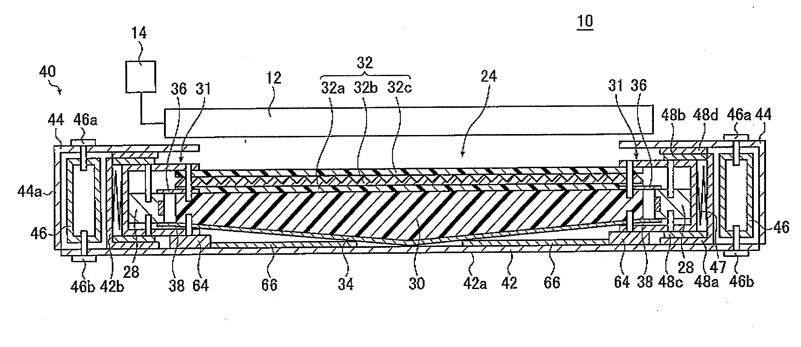
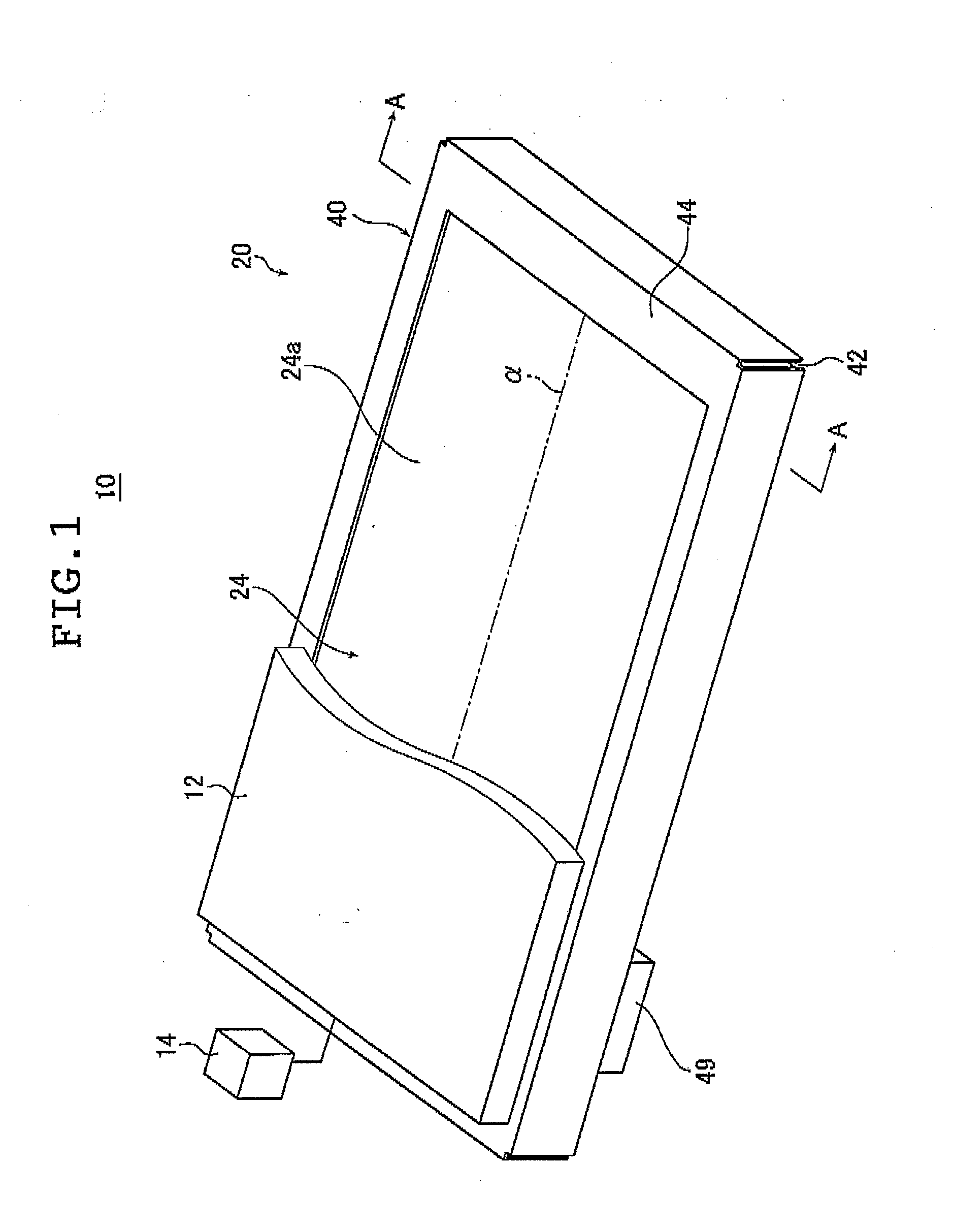
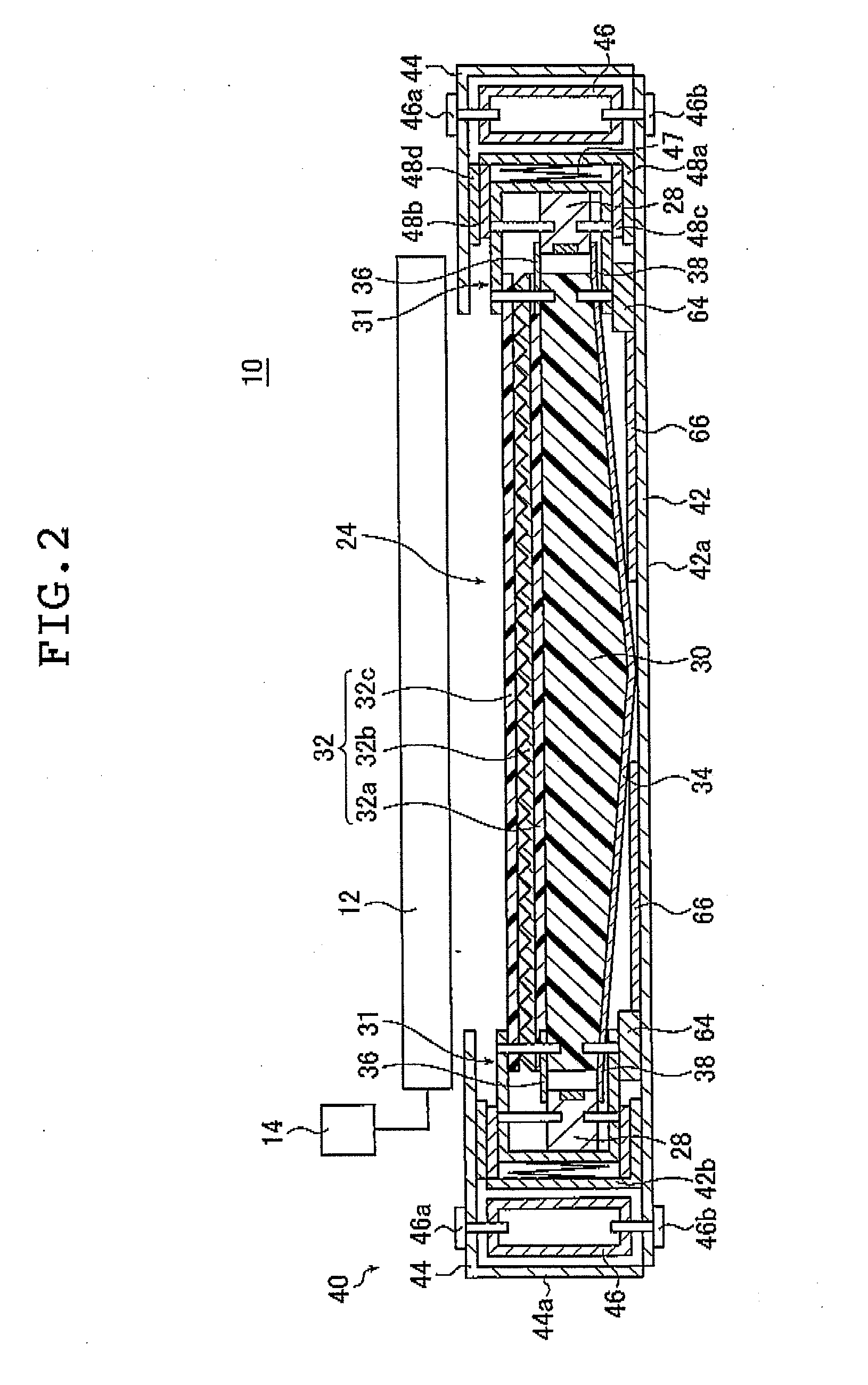
[0060]FIG. 1 is a schematic perspective view illustrating a liquid crystal display device provided with the planar lighting device of the present invention. FIG. 2 is a cross sectional view of the liquid crystal display device illustrated in FIG. 1 taken along line A-A. FIGS. 3A and 3B are views of modified examples of the liquid crystal display device illustrated in FIG. 2. FIG. 4 is a partially enlarged cross sectional view illustrating in detail a light guide plate illustrated in FIG. 2. FIG. 5A is a partially omitted plan view of the light guide plate and light sourc...


PUM


Abstract

A planar lighting device is capable of keeping the light entrance plane of the light guide plate spaced a constant distance from the light source and the light guide plate spaced a constant distance from the liquid crystal display panel even when the light guide plate expands, contracts or warps. This prevents break of the light source, decrease of light admission efficiency, occurrence of uneven brightness, and break of the liquid crystal display panel and permits a thin, larger, and lightweight design. The planar lighting device includes a fixing member for keeping them spaced from each other, a housing for accommodating the light source and the light guide plate, a sliding mechanism to elastically hold the fixing means against the housing while keeping the light source spaced a constant distance from the light guide plate, and a reinforcing member for reinforcing the housing.

Description

BACKGROUND OF THE INVENTION[0001]The present invention relates to a planar lighting device including light sources and a light guide plate for admitting light emitted by the light sources and emitting a light through the light exit plane thereof. The inventive planar lighting device is used for indoor and outdoor illumination or as a backlight to illuminate the liquid crystal display panel used in liquid crystal display devices or a backlight used for advertising panels, advertising towers, advertising signs, and the like.[0002]Liquid crystal display devices use a backlight unit for radiating light from behind the liquid crystal display panel to illuminate the liquid crystal display panel. A backlight unit is configured using optical members including a light guide plate for admitting light emitted by an illuminating light source and diffusing the light within the inside thereof to emit the light through a light exit plane, irradiating the liquid crystal display panel, a prism sheet...

Claims


Application Information

Patent Timeline
IPC IPC(8): F21V8/00H01L33/32H01L33/60
CPCG02B6/0046G02B6/005G02B6/0091G02B6/0085G02B6/0068
Inventor IWASAKI, OSAMU
Owner FUJIFILM CORP
Why Eureka
Try Eureka