
Pilot signal transmission method and radio communication apparatus

a radio communication apparatus and pilot signal technology, applied in the field of radio communication systems, can solve the problems of not becoming orthogonal and the inability to suppress inter-cell interference, and achieve the effect of reducing inter-cell interference of pilot signals and good cross-correlation characteristics

Active Publication Date: 2009-04-16
NEC CORP
View PDF6 Cites 32 Cited by
  • Summary
  • Abstract
  • Description
  • Claims
  • Application Information

AI Technical Summary

Benefits of technology

[0046]In order to solve the problems described above, it is an object of the present invention to provide a pilot signal transmission method and a radio communication apparatus in a mobile radio system, whereby when CAZAC sequences are transmitted as pilot signals and CDM is used as the user multiplexing method, the pilot signals of users different in bandwidth can be made orthogonal in a cell and inter-cell interference to pilot signals from another cell can be reduced.
[0062]Accordingly, all the sequence lengths for the pilot signal sequences can be made identical, hence it is possible to select sequences having good cross-correlation characteristics.
[0063]As has been described, the present invention is constructed such that, when pilot signal sequences which at least have either the first property that the self-correlation value when the phase difference is other than zero is equal to or lower than a predetermined threshold relative to the peak self-correlation value when the phase different is zero, or the second property that the cross-correlation value between the sequences that are equal in sequence length is smaller than the cross-correlation value between the sequences that are different in sequence length, are transmitted while using code division multiplexing as at least one of user multiplexing schemes, a system band as a frequency band usable in the system is divided into a plurality of frequency blocks having plural kinds of bandwidths; pilot signals of the plural frequency blocks are generated with a single carrier, using the pilot signal sequences having sequence lengths corresponding to the plural frequency blocks; and, the generated pilot signals are transmitted as the pilot signals corresponding individual users, with multicarriers using an arbitrary number of frequency blocks among the plurality of frequency blocks. Accordingly, it is possible to make the pilot signals of different users in the band orthogonal to each other and reduce inter-cell interference of pilot signals from other cells.

Problems solved by technology

In this case, there is the problem that the pilot signals for the users who perform pilot signals using different frequency blocks of continuous frequencies will not become orthogonal.
In other words, when CAZAC sequences used as pilot signals are different in sequence length, there is the problem that inter-cell interference cannot be suppressed.

Method used


Image

  • Pilot signal transmission method and radio communication apparatus
  • Pilot signal transmission method and radio communication apparatus
  • Pilot signal transmission method and radio communication apparatus

Examples


first embodiment

The First Embodiment Mode

[0080]FIG. 8 is a diagram showing the first embodiment mode of a mobile radio system in which a radio communication apparatus of the present invention is used.

[0081]As shown in FIG. 8, in this mode, in BS101 as a base station and a plurality of mobile stations MS102-105 for performing communications with BS101 in CL100 as a service area formed by BS101 are provided. Here, BS101 and MS102-105 are the radio communication apparatus of the present invention.

[0082]FIG. 9 is a diagram showing bands through which individual users transmit pilot signals and CAZAC sequences used thereupon in the mobile radio system shown in FIG. 8.

[0083]As shown in FIG. 9, the system band as the frequency band that is usable in the system is divided into frequency blocks B1 and B2. It is also assumed that every user uses a different band to transmit the data signal or control signal with a single carrier. In this case, all the users use identical CAZAC sequences having a sequence len...

second embodiment

The Second Embodiment

[0111]FIG. 14 is a diagram showing the second embodiment mode of a mobile radio system in which a radio communication apparatus of the present invention is used.

[0112]As shown in FIG. 14, in this mode, in BS101 and BS301 as base stations and a plurality of mobile stations MS102-105 and MS302-305 for performing communications with BS101 and BS301 respectively in CL100 and CL300 as service areas formed respectively by BS101 and BS301 are provided. Here, BS101, 301, MS102-105 and 302-305 are the radio communication apparatus of the present invention.

[0113]FIG. 15 is a diagram showing bands through which individual users transmit pilot signals and CAZAC sequences used thereupon in the mobile radio system shown in FIG. 14. Here, similarly to the conventional configuration, it is assumed that data signal or control signal is transmitted with a single carrier using frequency blocks having continuous frequencies.

[0114]In the first embodiment mode, the bands through whic...


PUM


Abstract

In a radio communication system, transmission of CAZAC sequences as the pilot signal sequences by using code division multiplexing as at least one of user multiplexing schemes, is done by dividing a system band as a frequency band usable in the system into frequency blocks B1 and B2 having bandwidths W1 and W2, generating the pilot signals of the frequency blocks B1 and B2 with a single carrier, using the pilot signal sequences having sequence lengths L1 and L2 corresponding to frequency blocks B1 and B2 respectively; and, transmitting the generated pilot signals as the pilot signals corresponding individual users, with multicarriers using an arbitrary number of frequency blocks among the plural frequency blocks

Description

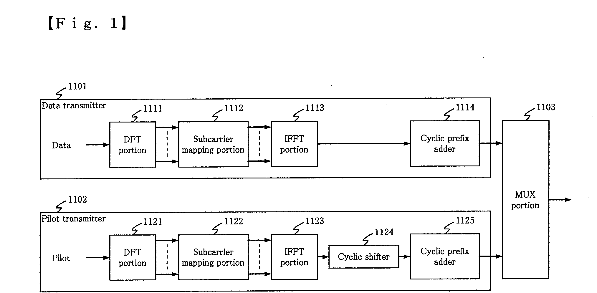
TECHNICAL FIELD[0001]The present invention relates to a radio communication system, and in particular relates to a pilot signal transmission method and radio communication apparatus that transmit a pilot signal in the uplink.BACKGROUND ART[0002]Recently, Beyond 3 G has been developed as the next-generation radio network which can establish seamless and safety connection between a plurality of radio communication systems including third generation mobile communications (3 G), wireless LANs and fourth generation mobile communications (4 G). As the uplink transmission scheme for the Beyond 3 G, use of a single carrier transmission scheme is considered (e.g., see literature ‘3GPP, “TR25.814 v1.2.2” March 2006’ (which will be referred to hereinbelow as literature 1)).[0003]FIG. 1 is a diagram showing a configuration of a transmitter based on a single carrier transmission scheme described in literature 1.[0004]The transmitter shown in FIG. 1 includes data transmitter 1101, pilot transmitt...

Claims


Application Information

Patent Timeline
IPC IPC(8): H04B7/216H04B1/707H04J13/00
CPCH04B2201/70701H04J13/0059H04L27/2613H04L5/0007H04L5/0048H04J13/0077H04B1/76H04B7/005H04L5/005H04W28/20
Inventor INOUE, TAKAMICHIKAKURA, YOSHIKAZU
Owner NEC CORP
Learn More