An Orthogonal Narrowband Waveform Design Method for Cooperative Spectrum Sensing

A collaborative spectrum sensing and waveform design technology, applied in transmission monitoring, electrical components, transmission systems, etc., can solve problems such as low power utilization and poor waveform orthogonality, and achieve high power utilization, high waveform orthogonality, The effect of good cross-correlation properties

Active Publication Date: 2017-11-07
HARBIN INST OF TECH
View PDF5 Cites 0 Cited by
  • Summary
  • Abstract
  • Description
  • Claims
  • Application Information

AI Technical Summary

Problems solved by technology

[0004] The purpose of the present invention is to solve the problems that the existing waveform design method has no limitation on side lobe, low power utilization rate and poor waveform orthogonality, and proposes an orthogonal narrowband waveform design method for cooperative spectrum sensing

Method used


Image

  • An Orthogonal Narrowband Waveform Design Method for Cooperative Spectrum Sensing
  • An Orthogonal Narrowband Waveform Design Method for Cooperative Spectrum Sensing
  • An Orthogonal Narrowband Waveform Design Method for Cooperative Spectrum Sensing

Examples


specific Embodiment approach 1

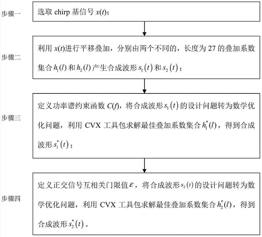
[0019] Specific implementation mode one: combine figure 1 Describe this embodiment, a kind of orthogonal narrow-band waveform design method oriented to collaborative spectrum sensing, it is characterized in that, a kind of orthogonal narrow-band waveform design method oriented to cooperative spectrum sensing is specifically carried out according to the following steps:

[0020] Step 1. Select the chirp base signal x(t);

[0021] Step 2: Use x(t) to carry out translation and superposition, respectively by two different superposition coefficient sets h with a length of 27 1 (l) and h 2 (l) Generate a synthetic waveform s 1 (t) and s 2 (t);

[0022] Step 3. Define the power spectrum constraint function C(f), and synthesize the waveform s 1 The design problem of (t) is transformed into a mathematical optimization problem, and the optimal stacking coefficient set is solved using the CVX toolkit get the best synthesized waveform

[0023] Step 4: Define the orthogonal sign...

specific Embodiment approach 2

[0024] Specific embodiment two, the difference between this embodiment and specific embodiment one is that the chirp base signal x(t) is selected in the step one; the specific process is:

[0025] The chirp base signal is expressed as:

[0026]

[0027] Among them, A is the amplitude of the chirp base signal, f 0 is the center frequency of the chirp base signal, k is the modulation frequency, T is the duration of the signal, e is the natural logarithm, j is the imaginary number unit, and t is time.

[0028] According to the fractional Fourier transform, the fractional Fourier transform of the chirp base signal x(t) is expressed as

[0029]

[0030] in, is the kernel function of fractional Fourier transform, where α is the rotation angle, α≠kπ, and u is the independent variable in the fractional domain;

[0031] According to the relationship between the fractional Fourier transform of the chirp base signal x(t) and the time-frequency distribution, when the rotation an...

specific Embodiment approach 3

[0035] Specific embodiment 3. The difference between this embodiment and specific embodiment 1 or 2 is that in the second step, x(t) is used for translation and superposition, and there are two different superposition coefficient sets h with a length of 27 1 (l) and h 2 (l) Generate a synthetic waveform s 1 (t) and s 2 (t); the specific process is:

[0036] Synthetic waveform s after weighted translation superposition 1 (t) and s 2 (t) can be expressed as:

[0037]

[0038]

[0039] Among them, x(t) is the chirp basis function; h 1 (l) is the synthetic waveform s 1The lth superimposition coefficient of the superimposed waveform in (t), -13≤l≤13; h 2 (l) is the synthetic waveform s 2 The lth superimposition coefficient of the superimposed waveform in (t), -13≤l≤13; h 1 (l) and h 2 (l) are evenly symmetrical about the origin; M=(L-1) / 2 is the number of chirp base signals superimposed on one side, M=13; L is the total number of signals of the superimposed waveform...


PUM


Abstract

An orthogonal narrow-band waveform design method oriented to cooperative spectrum sensing, and the invention relates to an orthogonal narrow-band waveform design method oriented to cooperative spectrum sensing. The purpose of the invention is to solve the problems that the existing waveform design method has no limitation on side lobe, low power utilization rate and poor waveform orthogonality. Realized by the following technical solutions: Step 1, select chirp base signal x(t); Step 2, use x(t) to carry out translation and superposition, respectively by two different superposition coefficient sets h1(l) and h2 whose length is 27 (l) Generate s1(t) and s2(t); step 3, define the power spectrum constraint function, convert the design problem of s1(t) into a mathematical optimization problem, and use the CVX toolkit to solve the best stacking coefficient set to obtain step 4 : define the threshold value of cross-correlation of orthogonal signals, convert the design problem of s2(t) into a mathematical optimization problem, and use the CVX toolkit to solve the best stacking coefficient set to obtain the present invention and apply it to the field of spectrum sensing.

Description

technical field [0001] The invention relates to an orthogonal narrowband waveform design method oriented to cooperative spectrum sensing. Background technique [0002] In order to meet people's increasing demand for communication speed, wireless spectrum resources are continuously allocated and authorized for use by different wireless communication systems. With the broadbandization of the network and the diversification of services, the existing fixed spectrum management mode makes wireless resources increasingly scarce. Considering that the division of spectrum resources has become increasingly saturated, cognitive radio technology is proposed as a technology that can flexibly use idle spectrum resources. In the cognitive radio system, according to different functions, it is divided into cognitive users and authorized users. Cognitive users can only access the spectrum for communication when they detect that authorized users do not use their assigned spectrum resources. O...

Claims


Application Information

Patent Timeline
Patent Type & Authority Patents(China)
IPC IPC(8): H04B17/382
Inventor 吴宣利韩杏玲吴玮李欣悦付楠楠马哲明
Owner HARBIN INST OF TECH
Why Eureka
Try Eureka